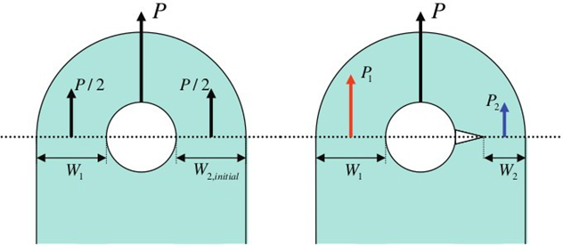
The crack growth solver can redistribute a load during crack growth. Figure 1 shows a typical example of load shedding/redistribution due to a growing crack.
In the case of a single crack in a lug, the cracked section W2 becomes less rigid
than the un-cracked section W1, and part of the applied load is transferred to
section W1. This situation would not happen in the case of two symmetric cracks
because both sections have to hold the same amount of load equal to the half of the
load applied to the lug.Figure 1. Schematic Illustration of the Load Shedding Effect in an Attachment
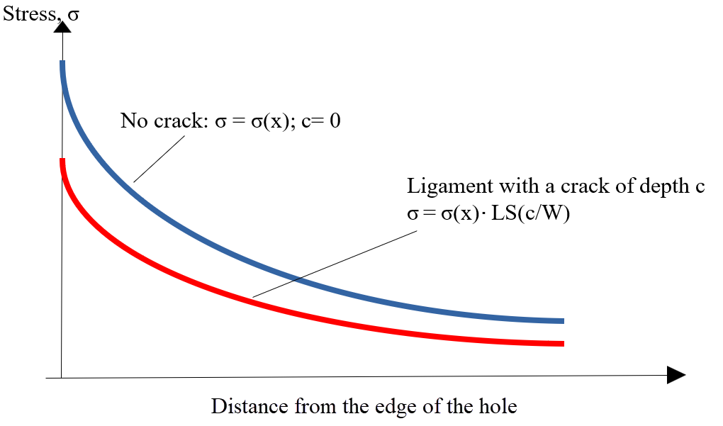
Lug It has been shown using finite element analysis that this effect is relatively
small, as long as crack stays quarter-elliptical, but becomes significant when the
crack breaks through the entire thickness of the lug.Figure 2. The Load Shedding/Redistribution Effect On the Stress Distribution in the
Cracked Ligament Introduction of the load shedding parameter, , enables the estimation of the amount of load taken
by the cracked section ‘W2’ and the estimation of the actual load. Once the shedding
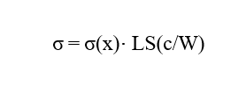
parameter LS is estimated, the shedding parameter could be used to reduce stress at
the crack (Figure 2).Figure 3.
Where,
Crack length
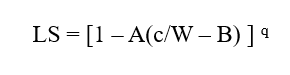
Out of test data, the load shedding parameter was fitted into the following
expression 5:Figure 4.
A, B, and q are required inputs. In this particular example, , and were taken.
In actual crack growth calculation, the shedding parameter is used to reduce stress
intensity factor:Figure 5.
1 Noroozi AH, Glinka
G, Lambert S, A two-parameter driving force for fatigue crack growth analysis.
Int J Fatigue 2005;27:1277–1296.
2 Mikheevskiy S,
Bogdanov S, Glinka G, Analysis of fatigue crack growth under spectrum loading –
The UniGrow fatigue crack growth. Theoretical and Applied Fracture Mechanics
2015;79;25–33
3 Noroozi AH, Glinka
G, Lambert S, Prediction of fatigue crack growth under constant amplitude
loading and a single overload based on elasto-plastic crack tip stresses and
strains. Engineering Fracture Mechanics 2008;75;188–206
4 A.K. Vasudevan, K.
Sadananda, N. Louat, Reconsideration of Fatigue Crack Closure. Scripta
Metallurgica et Materialial 1992;27;1673-1678.
5 Mikheevskiy S,
Glinka G, Algera D, Analysis of fatigue crack growth in an attachment lug based
on the weight function technique and the UniGrow fatigue crack growth model. Int
J Fatigue 2012;42:88- 95.
6 Cordes T, Norton E,
Brown H, Munson K, Comparison of Total Fatigue Life Predictions of Welded and
Machined A36 Steel T-Joints. SAE Technical Paper 2019-01-0527, 2019