From the Home tools, Files tool group, click the Open Model tool.
Figure 1.
The Open Model/Results
Files dialog opens.
Browse for and select HL-2010\sidedoor_gp.hm as
the model file.
Browse for and select HL-2010\sidedoor_gp.h3d as
the result file.
Click Apply.
Figure 2.
Identify Weld Lines
Click the Mark Welds tool.
Figure 3.
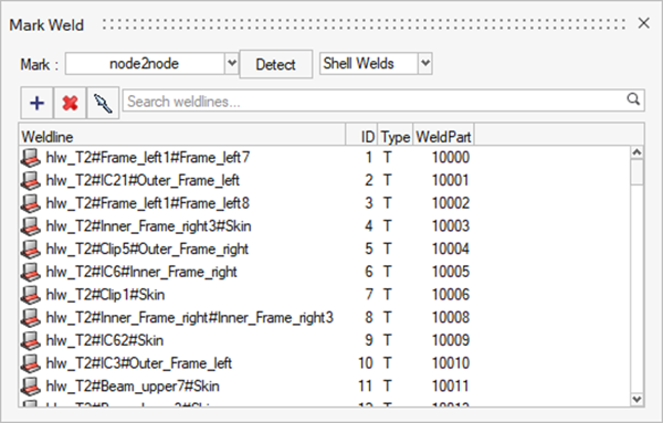
The Mark Weld dialog opens.
Click Detect.
HL-WC identifies the welds present in the model
and highlights them in red.
Once detection is complete, a
message stating the number of weld lines identified is
displayed.
Figure 4.
The weld line browser is
updated.Figure 5.
Screen Welds
Click the Inspect tool.
Figure 6.
The Inspect Browser dialog opens.
Select Subcase 1 (Cruise) from the Subcase drop-down
menu.
Enter a threshold value of 100.
Figure 7.
Click Inspect.
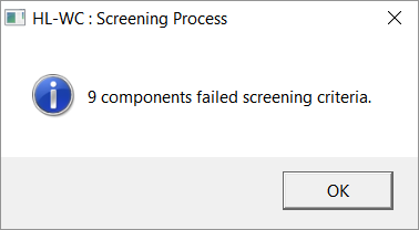
Once the screening is complete, a dialog will display the number of
failed weld lines.Figure 8.
Click OK.
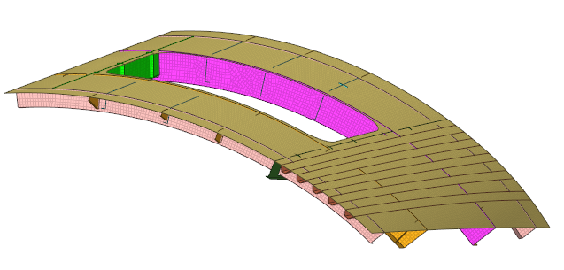
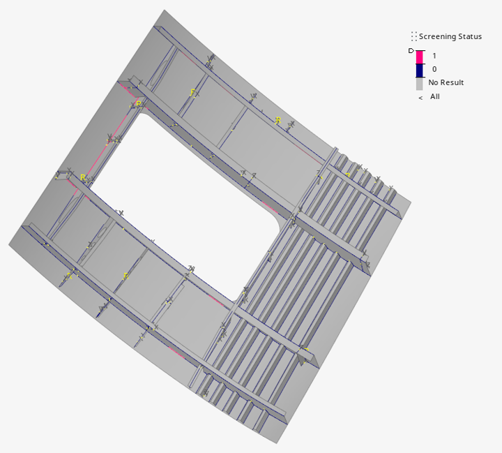
The legend on the right side of the modeling window
colors failed weld lines in pink.Figure 9.
Optional: Click in the
dialog to plot the ratio of the von Mises stress value of an element and the
threshold value you provided.
Exit the Inspect Browser dialog.
Define a Weld Specification
Click the Specifications tool.
Figure 10.
The Weld Specification dialog opens.
Select FKM from the Regulation drop-down menu.
Figure 11.
Click Apply.
Parameters are applied to all the weld line
evaluation points.
Click OK.
Review Evaluation Points
Click the Points tool.
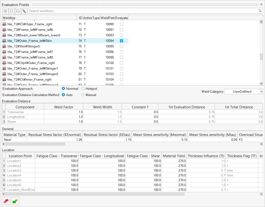
Figure 12.
The Evaluation Points dialog opens.
Select hlw_T2#Frame_left3#Skin from the weld line list.
Note: The Evaluate checkbox should be activated. Any weld lines that are marked as critical in the screening
process are automatically selected in the Evaluation
Points dialog.
Review the classification parameters.
The classification parameters for each weld vary depending on the weld type
and the weld regulation selected.Figure 13.
Review other weld lines at your own discretion then exit
the dialog.
Create and Assign a Material
Click the Material tool.
Figure 14.
The Assign Material dialog opens.
Click to select all the
parts.
Click the My Material tab.
Click .
A new material named Material2 is created.
Modify the material parameters.
Set the Tensile Strength to 690.
Set the Yield Strength to 360.
Set the Normal Fatigue Limit to 310
Set the Shear Fatigue Limit to 180.
Accept all other default parameters and click Plot &
Save.
Figure 15.
Right-click on Material2 and select Add to
Assign Material List.
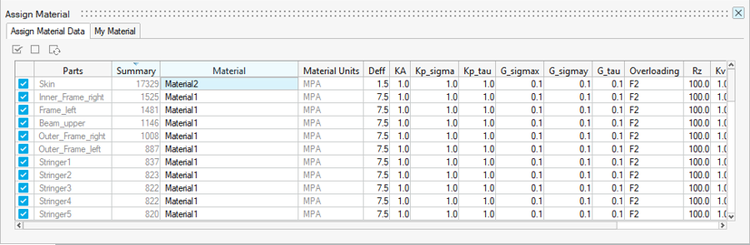
Return to the Assign Material Data tab.
For the part Skin, select Material2 from the Material
drop-down menu.
Accept the default materials and parameters for all other parts.
Figure 16.
Exit the dialog.
Evaluate and View Results
From the Evaluate tool group, click the
Run Analysis tool.
Figure 17. By default, an event with all subcases is created. The created event will
compare the subcases placed within an event to create the maximum range.
The Evaluate Welds dialog opens.
Optional: Enter a name for the run.
Optional: Edit the default event or create a new subcase through the LoadMap
context.
Select Both Welds & Unwelded for the evaluation
domain.
Verify Stress Combination is set to Tensor
components.
Figure 18.
Click Evaluate.
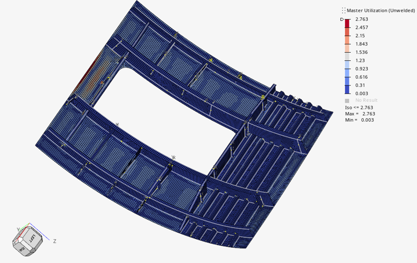
Both the welds and unwelded elements are evaluated.Figure 19.
By default, Max Utilization - Unwelded is contoured.
In the Results Explorer, select Top
Layer and MinStress_X from the contour
result drop-down menus and click .
The selected result type is contoured.Figure 20.
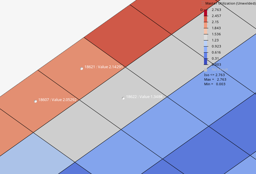
Add tags to elements.
In the Results Explorer, select
MasterUtilizationUnWelded from the contour
result drop-down menu and click .
Select elements to tag.
Click on the
entity selector.
The selected elements are tagged with IDs and utilization
values.Figure 21.

 The Mark Weld dialog opens.
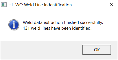
 The Inspect Browser dialog opens.
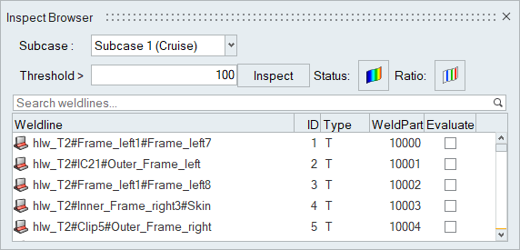
 in the
dialog to plot the ratio of the von Mises stress value of an element and the
threshold value you provided.
in the
dialog to plot the ratio of the von Mises stress value of an element and the
threshold value you provided.
 The Weld Specification dialog opens.
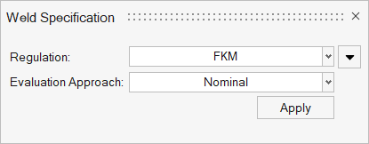


 to select all the
parts.
to select all the
parts.
 .
A new material named Material2 is created.
.
A new material named Material2 is created.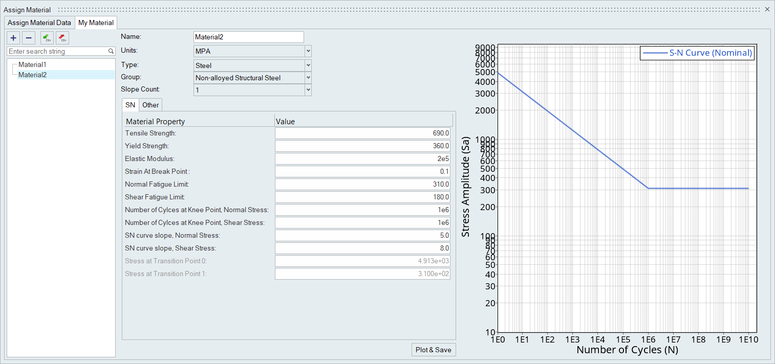
 The Evaluate Welds dialog opens.
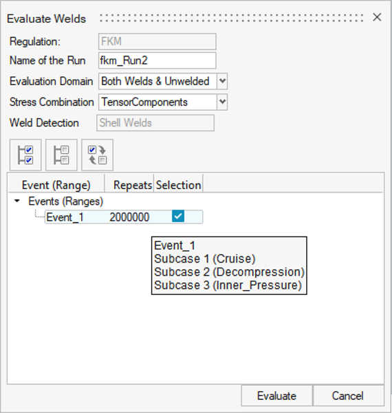
 .
The selected result type is contoured.
.
The selected result type is contoured.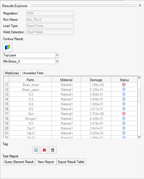
 on the
entity selector.
The selected elements are tagged with IDs and utilization values.
on the
entity selector.
The selected elements are tagged with IDs and utilization values.