MV-1051: Understanding Sequential Simulation
In this tutorial, you will learn how to build a model with sensor elements to capture the state of a body, use the sensor signal to activate some joints and deactivate others, and carry out a sequential simulation.
Sequential Simulation allows you to write simulation instructions to change the model, modify the solver settings and submit analyses.
- Fixed joint definition between non-coinciding points using marker definitions.
- Using a sensor to activate the joint when two markers coincide during simulation.
- Using Templex statements to:
- Deactivate a fixed joint when markers are non-coincident.
- Activate a fixed joint when markers coincide.
- Simulate until t = 5.00 seconds.
Create Joints, Markers, and Sensors
- Start a new MotionView session.
-
From the Standard toolbar, click Open Model
 .
.
OR
From the File menu, select to open the model Sequential_simulation.mdl.
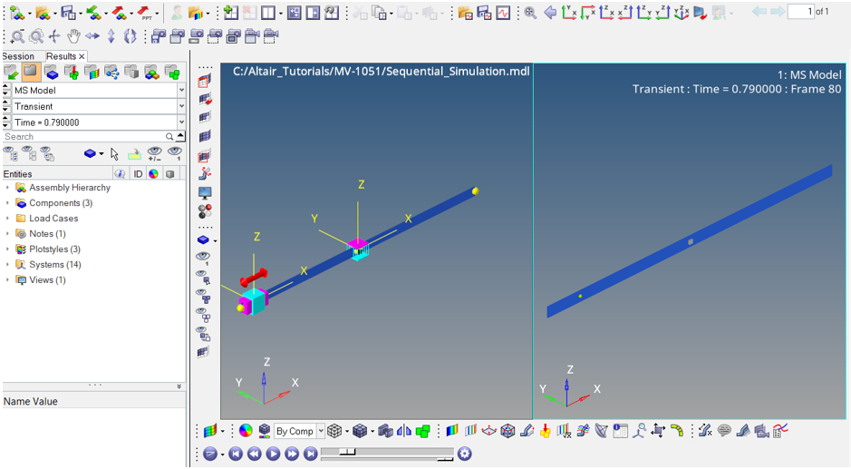
The model contains two bodies, namely a slider and a picker. You need to create markers, joints, and a sensor as well as use Templex statements to perform a sequential simulation.Figure 1. 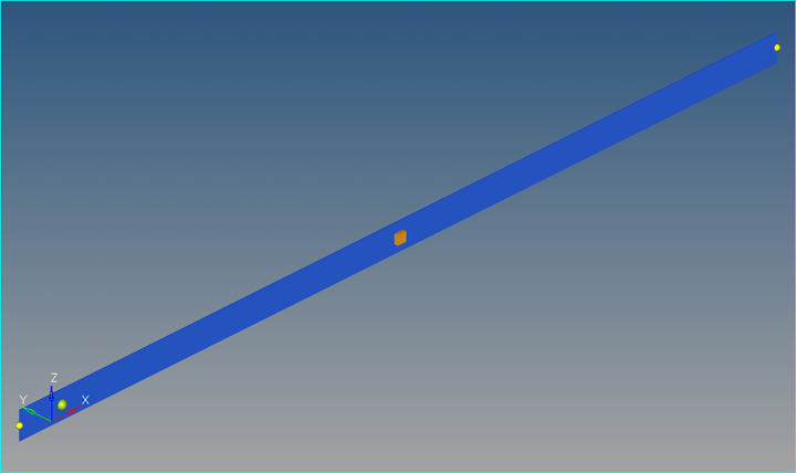
-
From the Project Browser, right-click on
Model and select (or right-click Joints
 from the toolbar).
- Under Type, select Translational Joint. Label the joint slider trans.
-
Make the following selections:
-
Define the Alignment axis using the point slide
end.
Figure 2. 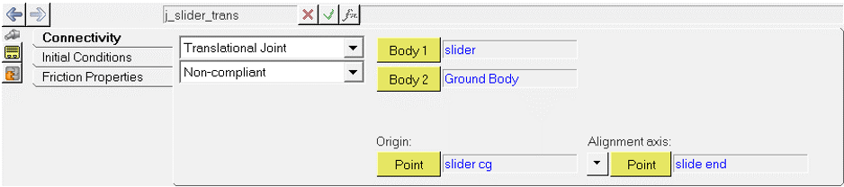
-
Define the Alignment axis using the point slide
end.
- Add another joint. For Type, select Fixed Joint and label the joint picker rest fix.
-
Make the following selections:
- For Body 1, select picker.
- For Body 2, select Ground Body.
- For Origin, select part fix.
This joint will be deactivated when the slider body coincides with the picker body during simulation.Figure 3. 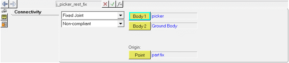
When you create a fixed joint between the slider and the picker and they come in contact, you need to define two markers which are initially not coincident, but coincide during the course of simulation. Creating a joint based on markers must be done using Templex, as it is not possible to create it from the user interface.
-
From the Project Browser, right-click
Model and select (or right-click Marker
 from the toolbar). Label it Marker
Slider Track and set the properties as shown in the image
below:
from the toolbar). Label it Marker
Slider Track and set the properties as shown in the image
below:
Figure 4. 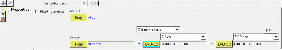
-
Similarly, create another marker with the label Marker Picker
Track and set the properties of the markers as shown in the
image below:
Figure 5. 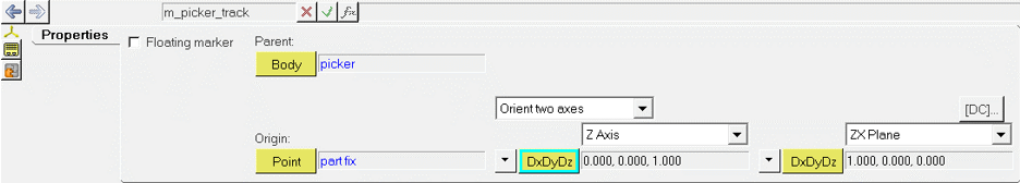
-
From the Project Browser, right-click
Model and select (or right-click Sensor
 from the toolbar) to add a new sensor.
-
From the Signal field, select the type as Expression and
enter the following expression:
`DX({m_slider_track.idstring},{m_picker_track.idstring})` - In the Compare To field, enter 0.0010 for the Value and 0.0010 for Error. Set Respond if to Signal is greater than VALUE - ERROR.
-
In the Response field, select Return to Command
File.
This directs the solver to look into the template for further instruction on how to proceed once the signal is attained.
-
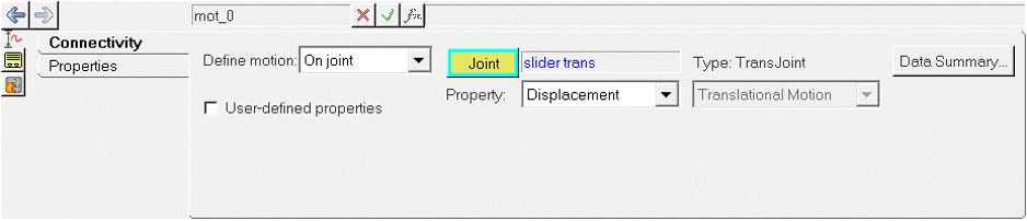
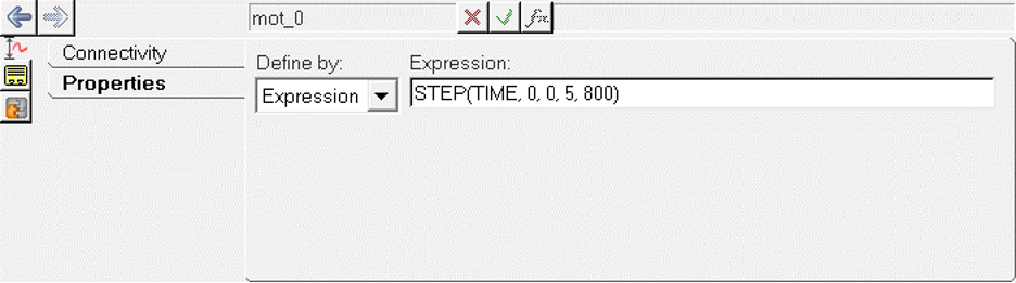
From the Project Browser, right-click on
Model and select (or right-click Motion
 from the toolbar. Set the
properties as shown in the figure below using the following expression:
from the toolbar. Set the
properties as shown in the figure below using the following expression:
`STEP(TIME, 0, 0, 5, 800)`
Create a Fixed Joint Between Two Non-coincident Markers Using Templex
-
To create a fixed joint between the slider and picker that is activated once
the distance between the slider and picker is zero, from the Project Browser, right-click on Model and
select (or right-click Template
 from the toolbar).
-
Label it Fixed Joint Defn. For Type, select
Write text to solver input deck. Enter the following
commands as they are listed below in the same order.
<Constraint_Joint
id                  = "5000"
type                = "FIXED"
i_marker_id         = "{the_model.m_slider_track.idstring}"
j_marker_id         = "{the_model.m_picker_track.idstring}"
/>
The panel should look like this:Figure 8. 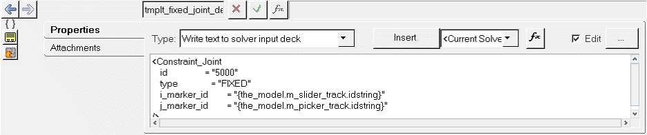
Create a Template to Define the Sequential Simulation
- Deactivate Joint between Slider and Picker for the initial simulation.
- Perform a transient analysis for 3.5 seconds.
- Activate Joint between Slider and Picker.
- Deactivate Joint between Picker and Ground.
- Deactivate the Sensor Element.
- Run a transient analysis for 5 seconds.
-
From the Project Browser, right-click on
Model and select (or right-click Template
from the toolbar).
- Set the Type as Write text to solver command file.
- Type the following commands as listed below.
<Deactivate
element_type = "JOINT"
element_id   = "5000"
/>
<Simulate
analysis_type       = "Transient"
end_time            = "3.5"
print_interval      = "0.01"
/>
<Deactivate
element_type = "JOINT"
element_id   = "{the_model.j_picker_rest_fix.idstring}"
/>
<Deactivate
element_type = "SENSOR"
element_id   = "{the_model.sen_0.idstring}"
/>
<Activate
element_type = "JOINT"
element_id   = "5000"
/>
<Simulate
analysis_type       = "Transient"
end_time            = "5."
print_interval      = "0.01"
/>
<Stop/>
Run the Simulation and Animate the Results
-
Click Run Solver

-
Click the Save and run current model
 and enter a name for the solver run file.
- Set End time as 5 and the Print interval as 0.01.
- Click Run.
-
Once the solver procedure is complete, the Animate button on the Main tab is
activated. Click Animate to animate the model. Click
 to start the animation and
  to stop the animation.
Figure 9.