
MV-1030: Create a System Definition Using the MotionView GUI
In this tutorial you will learn how to create systems using the MotionView graphic user interface, export a system definition to a file, and instantiate a saved definition in a model.
Create a System Instance
In this step, you will create a system instance.
-
Open the Add System/Assembly dialog in one of the
following ways:
- In the Project Browser, right-click on Model and select .
- On the Container Entity toolbar, right-click the
 (System/Assembly panel) button.
- In the dialog, click the System radio button.
- In the Add System dialog, specify the Variable as sys_pendu, the Label as Pendulum, and the Definition Name as def_sys_pendu.
-
Click OK.
This will add the Pendulum system
 to the model and display the
system's panel.
to the model and display the
system's panel.
Add Attachments to the System
In this step you will create two attachments for the Pendulum system.
- From the Attachments tab, click on the Add button.
- In the dialog, specify the Label as Attachment Point and the Variable as arg_p. Verify that Type is set to Single only.
- From the drop-down menu, select Point.
- Click OK.
-
Use steps 1
through 4 to
create a second attachment.
-
From the drop-down menu, select Body.
Figure 1. 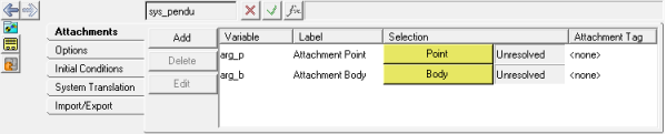
Note: These attachments will be used to attach this system to other model entities. Notice that both are currently Unresolved, meaning they are not yet referring to another entity in the model.
-
From the drop-down menu, select Body.
-
Double-click the
 collector.
-
In the Select a Point dialog, click Global Origin.
Figure 2. 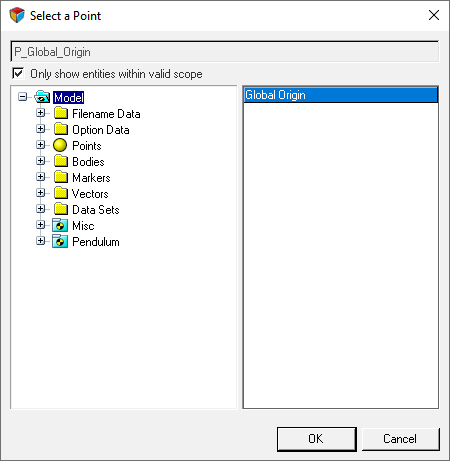
- Click OK.
-
Double-click the
 collector.
- In the dialog, click Ground Body.
- Click OK.
Add a Point to the System
In this step you will add a point to the Pendulum system.
- In the Project Browser, click Pendulum.
-
Open the Add Point or PointPair dialog in one of the
following ways:
- Right-click on Pendulum and select .
- On the Reference Entity toolbar, right-click the
 (Points) icon.
-
In the dialog, specify the Label as Mass CG and the
Variable as p_cg. Verify that Type is set to
Single.
Figure 3. 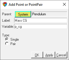
- Click OK.
-
From the Properties tab, click the X Coordinate field.
Then click the
 button.
This will display the Expression Builder.
button.
This will display the Expression Builder. - Delete 0.0 from the Expression area (located at the top of the dialog)
- From the Model Tree, expand the Pendulum Attachments Attachment Point folders and select x.
-
Click the Add button.
Figure 4. 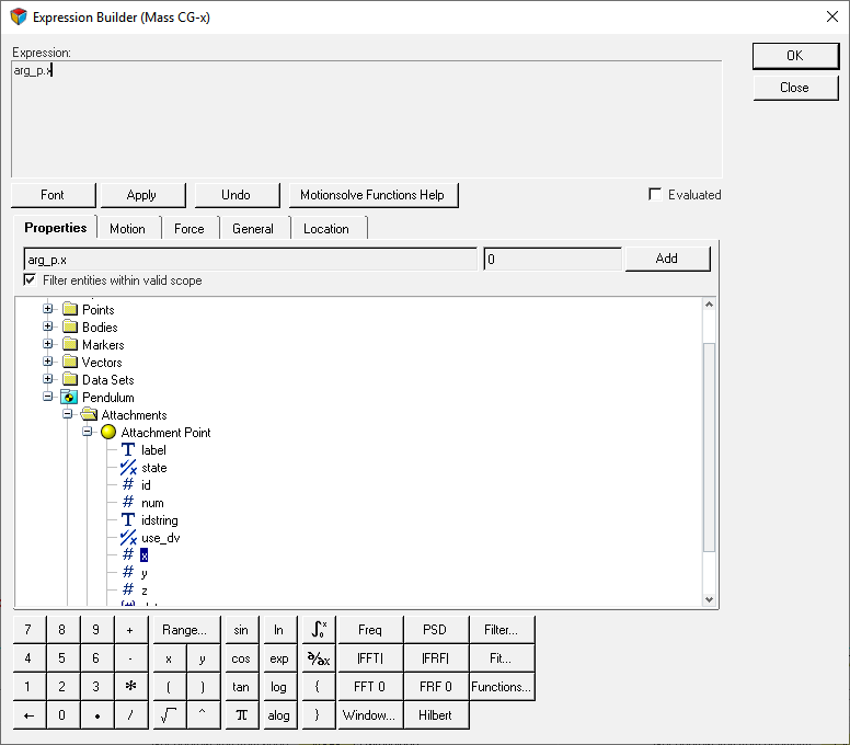
The expression arg_p.x will automatically fill the Expression area. -
Add +50 to the epression.
Figure 5. 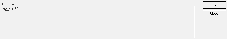
-
Click OK to close the
dialog.
This step will parameterize Mass CG with regard to the X coordinate of the Attachment Point. It is placed at a distance of 50 length units in the X direction.
-
Repeat steps 5
through 10 for the
Y and Z coordinates.
-
For the Z coordinate, specify the expression as
arg_p.z+100.
Note: You can also add the Y and Z coordinate expressions by copying the X coordinate expression and editing it.
Figure 6. 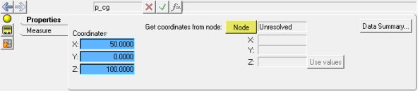
Note: the background color of the field changes for parametric expressions.
-
For the Z coordinate, specify the expression as
arg_p.z+100.
Add a Body to the System
In this step you will add a body to the Pendulum system.
- In the Project Browser, click Pendulum.
-
Open the Add Body or BodyPair dialog in one of the
following ways:
- Right-click on Pendulum and select .
- On the Reference Entity toolbar, right-click the
 (Bodies) icon.
- In the dialog, for Label enter Mass and for Variable enter b_mass. Click OK.
-
In the Properties tab:
- Clear the Get Properties from associated Graphic(s) check box.
- Specify the Mass as 1, and the Ixx, Iyy, and Izz Inertia properties as 1000.
Figure 7. 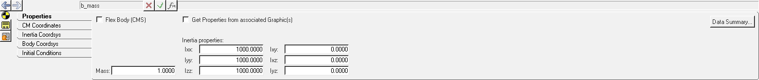
- In the CM Coordinates tab, check the Use center of mass coordinate system option.
-
Under Origin, double-click on
 .
.
-
In the dialog, select Mass CG and click
OK.
Figure 8. 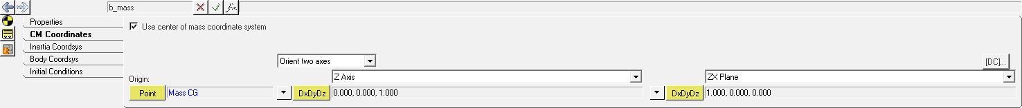
Add Graphics to the System
In this step, you will add graphics to the Pendulum system.
- In the Project Browser, click Pendulum.
-
Open the Add Graphic or GraphicPair dialog in one of the
following ways:
- Right-click on Pendulum and select .
- On the Reference Entity toolbar, right-click the
 (Graphics) icon.
- In the dialog, specify the label as Rod, the Variable as gcyl_rod, and the Type as Cylinder. Then click OK.
-
In the Graphics panel, configure the Connectivity tab.
-
Under Parent, double-click the
 collector.
-
Under Origin, double-click the collector.
-
Under Direction, double-click the collector.
-
In the dialog, specify the Attachment Point and
click OK.
Figure 9. 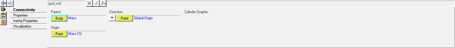
-
Under Parent, double-click the
- In the Properties tab, for Radius 1 enter 2.
-
Repeat step 2 to
add a sphere graphic.
- In the dialog, for Label enter Mass.
- For Variable, enter gsph_mass.
- For Type, select Sphere.
- Click OK.
-
In the Graphics panel, under the Connectivity tab specify the Parent body as
Mass and the Origin point as Mass
CG.
Figure 10. 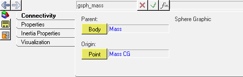
-
In the Properties tab, specify a Radius of 25.
Figure 11. 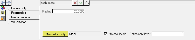
Add a Joint to the System
In this step you will add a revolute joint to the Pendulum system.
- In the Project Browser, click Pendulum.
-
Open the Add Joint or JointPair dialog in one of the
following ways:
- Right-click on Pendulum and select .
- On the Reference Entity toolbar, right-click the
 (Joints) icon.
- In the dialog, for Label enter Pivot, for Variable enter j_pivot, and for Type select Revolute Joint.
- Click OK.
-
In the Joints panel, from the Connectivity tab double-click on
 .
.
- From the Select a Body dialog, select Mass and click OK.
-
Double-click
 .
.
-
From the dialog, expand the folders and select Attachment Body.
Figure 12. 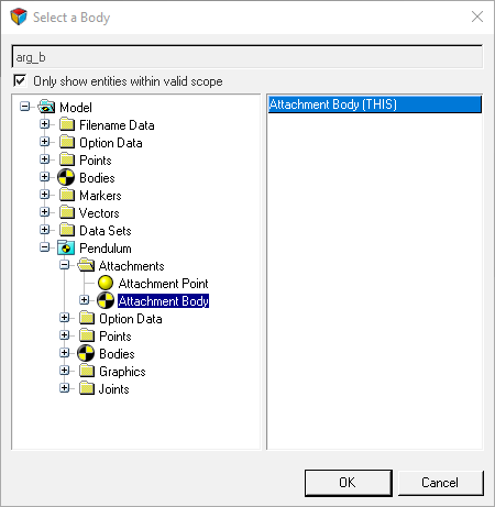
Tip: You can also click the Global Triad and pick Ground Body via the Attachment Body. -
Under Origin, double-click the
collector.
- From the dialog, expand the folders and select Attachment Body.
- Under Alignment Axis, use the drop-down menu to change the collector to from Point to Vector.
-
Double-click
 and select Global Y.
-
Click
 (Save model) and save the file
as pend_gui.mdl to your <working
directory>.
(Save model) and save the file
as pend_gui.mdl to your <working
directory>.
Export the System Definition
In this step you will learn how to export your system definition to your <working directory>.
- In the Project Browser, click Pendulum.
- In the Systems/Assembly panel, click the Import/Export tab.
-
Click the Export radio button.
Figure 13. 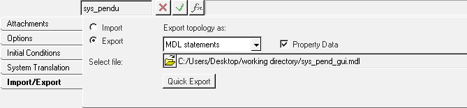
-
Click the
 (file browser) and browse to your
<working directory>.
(file browser) and browse to your
<working directory>.
- Specify the name of the file as sys_pend_gui.mdl and click Save.
-
Open sys_pend_gui.mdl in the text editor.
The system definition content will look like the example shown below:
*DefineSystem( def_sys_pendu, arg_p, arg_b )
*Attachment( arg_p, "Attachment Point", Point, "Select attachment.",
P_Global_Origin, )
*Attachment( arg_b, "Attachment Body", Body, "Select attachment.",
B_Ground, )
*SetDefaultSystemInstance( sys_pendu, "Pendulum" )
*Point( p_cg, "Mass CG" )
*Body( b_mass, "Mass", p_cg, , , , )
*Graphic( gcyl_rod, "Rod", CYLINDER, b_mass, p_cg, POINT, arg_p, 2.0,
gcyl_rod.r1, , 0.0, CAPBOTH )
*Graphic( gsph_mass, "Mass", SPHERE, b_mass, p_cg, 25.0 )
*RevJoint( j_pivot, "Pivot", b_mass, arg_b, arg_p, VECTOR, V_Global_Y
)
*SetPoint( p_cg, arg_p.x+50, arg_p.y,
arg_p.z+100 )
*SetBodyInertia( b_mass, 1.0, 1000.0, 1000.0,
1000.0, 0.0, 0.0, 0.0 )
*Set( b_mass.usecm, true )
*EndDefine()
Note: The Export option is only available for Systems and Analyses. For other definitions like Datasets or Templates, the definition can be copied from the model .mdl file.
Instantiate the System Definition
In this step you will learn how to instantiate a system definition.
- In the Project Browser, select the Model system.
- In the Systems/Assembly panel, click the Import/Export tab.
- Click the Import radio button.
-
Click the (file browser) and browse to your
<working directory>.
-
Select the sys_pend_gui.mdl file and click
Open.
Figure 14. 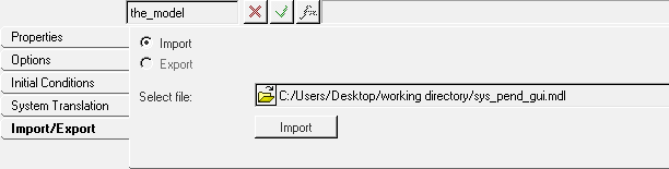
- Click the Import button.
- In the dialog, select def_sys_pendu.
-
Change the Label to Pendulum 2 and the Variable to
sys_pendu_2.
Figure 15. 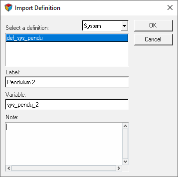
-
Click OK.
This will instantiate the definition. Pendulum 2 will appear in your Project Browser.
- Click on Pendulum 2.
-
In the Attachments tab, resolve the and attachments.
-
Double-click the collector.
-
In the Model Tree, click . Then click OK.
Figure 16. 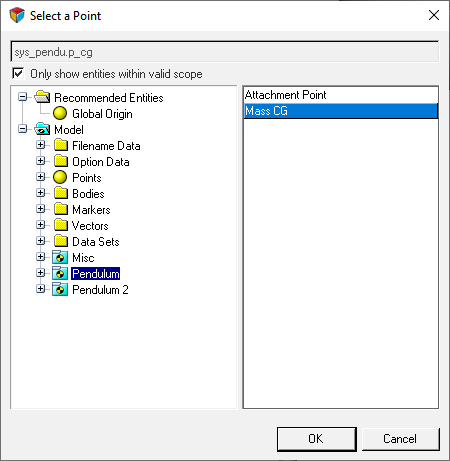
-
Double-click the collector.
-
Double-click the
-
Save the model to your <working directory> as
pend_2_gui.mdl.
You can reuse the same system definition to instantiate several times either within the same model or in a different model.