Defining a Cable Bundle
Define a cable bundle that may consist of multiple defined cables (for example, single conductors, coaxial cables, ribbon cables, twisted pairs, other cable bundles and non-conducting elements) and that are embedded in a medium with an optional shield.
Note: The following shield types are supported for cable bundles:
- Insulated, embedded in background medium (sheath/jacket)
- Not shielded, embedded in a dielectric
- Not shielded, embedded in background medium
- Shielded, dielectric filled
-
On the Cables tab, in the
Definitions group, click the
 Cable Bundle icon.
Figure 1. The Create Bundle dialog. 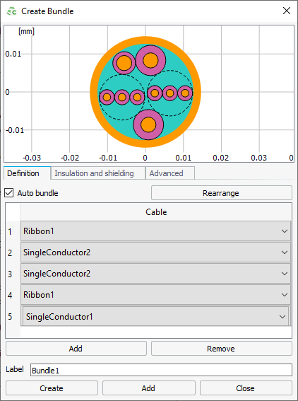
-
On the Bundle tab, bundle the cables using one of the
following methods:
- To create a cable bundle where the exact orientation of the cable in the
bundle is unknown or not relevant, select the Auto
bundle check box.
- Click the Rearrange button to place the cables in a new random location inside the bundle.
- To specify the location and orientation of the cables inside the cable
bundle, clear the Auto bundle check box.
- Specify the Offset X, Offset Y and Rotation of each cable contained in the bundle.
- To create a cable bundle where the exact orientation of the cable in the
bundle is unknown or not relevant, select the Auto
bundle check box.
-
From the Cable
drop-down list, specify the cables contained in the bundle using
one of the following methods:
- To specify a predefined cable, select the cable you want to add.
- To specify a cable, not yet defined in the model, click the
 icon to define a cable type.
-
On the Insulation and shielding tab, from the
Insulation medium
drop-down list, select one of the following:
- To specify the insulation medium consisting of a predefined dielectric, select the dielectric.
- To specify the insulation medium consisting of dielectric, which is not
yet defined in the model, click the
 icon to define a dielectric or add a dielectric
from the media library.
icon to define a dielectric or add a dielectric
from the media library.
-
On the Insulation and shielding tab, to specify the
Outer radius, select one of the following:
- To allow CADFEKO to calculate the outer radius of the cable bundle, select the Compute automatically check box.
- To manually specify the outer radius of the cable bundle in the Outer radius field, clear the Compute automatically check box.
For shield type 1, specify the Shield for the cable bundle.
Note: If a
braided shield is applied to the cable bundle the outer radius should be inside
the stretching limits defined for the braided shield.
-
On the Insulation and shielding tab, under
Shielding, from the Shield
drop-down list, select one of the following:
- To add an outer cable shield consisting of a predefined shield, select a cable shield.
- To add an outer cable shield consisting of a shield, which is not yet
defined in the model, click the icon to define a new cable shield.
-
Under Insulation layer (coating), specify the
following:
- To add a coating, select the Apply
coating check box.
- From the Medium drop-down list, specify the coating medium.
- In the Thickness field, specify the coating thickness.
- To remove the coating, clear the Apply coating check box.
- To add a coating, select the Apply
coating check box.
-
On the Advanced tab, under Twist,
from the Turn direction
drop-down list select one of the following:
- To define a bundle with no twist, select No twist.
- To define a bundle turning right, leading away from you, select Right handed.
- To define a bundle turning left, leading away from you, select Left handed.
- On the Advanced tab, under Twist, in the Pitch length field, enter the axial length required to complete one revolution of a cable in the bundle around the diameter of the bundle.
- In the Label field, add a unique label for the cable bundle.
- Click Create to create the cable bundle and to close the dialog.