HL-T: 2000 The Basics of HyperLife Weld Certification (DVS 1612)
This tutorial guides you through a step-by-step process that covers all the major
functionalities of HL-WC. By working through the tutorial, you can
quickly learn the tool and start using HL-WC to evaluate the welded
connections in your FE models using standard weld evaluation methods.
Before you begin, copy the file(s) used in this tutorial to your
working directory.
From the Home tools, Files tool group, click the Open Model tool.
Figure 1.
The Open Model/Results
Files dialog opens.
Browse for and select HL-2000\sidedoor_gp.hm as
the model file.
Browse for and select HL-2000\sidedoor_gp.h3d as
the result file.
Click Apply.
Figure 2.
Identify Weld Lines
Click the Mark Welds tool.
Figure 3.
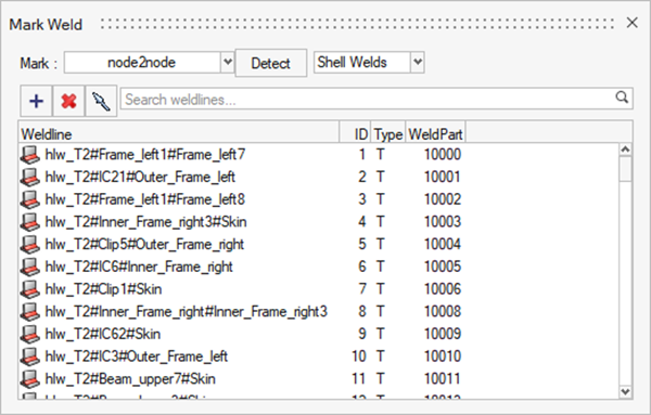
The Mark Weld dialog opens.
Click Detect.
HL-WC identifies the welds present in the model
and highlights them in red.
Once detection is complete, a
message stating the number of weld lines identified is
displayed.
Figure 4.
The weld line browser is
updated.Figure 5.
Add a Weld Line Manually
Click the Mark Welds tool.
Figure 6.
The Mark Weld dialog opens.
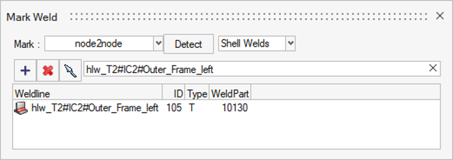
Enter hlw_T2#IC2#Outer_Frame_left in the search text box and
press Enter.
Figure 7.
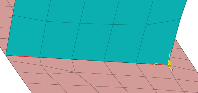
Right-click on the weld line and select Isolate > Weld + Comp from the context menu.
The weld line and its attached components are
isolated in the modeling window.
Rotate the model and zoom in closer to view the weld line
clearly.
Figure 8.
In the Mark Weld dialog, right-click on
hlw_T2#IC2#Outer_Frame_left and select
Delete from the context menu.
The weld line is deleted from the
model.
In the Mark Weld dialog, click .
An entity selector appears.
Select the starting and ending nodes of the weld path as shown in the image
below.
Figure 9.
The nodes in between the starting and ending nodes should be selected
automatically.
Click OK in the Advanced Selection
dialog then click on the entity selector.
The newly created weld line is displayed in the
Mark Weld dialog.Figure 10.
The weld line is also added to the WeldLines folder
in the HyperLife Model Browser.
Right-click on any weld in the dialog and select Show
All to return to the full model view.
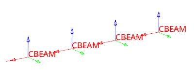
Modify a Weld Line
In the Mark Weld dialog, right-click on the first weld line, hlw_T2#Frame_left1#Frame_left7,
and select Isolate > Weld + Comp.
This lets you visualize the weld line and the two
connected components in the modeling window.
Right-click again on the same weld line and select Isolate > Weld + Systems.
The systems of the individual segments that make up the weld line are isolated.Figure 11.
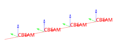
Again, right-click on hlw_T2#Frame_left1#Frame_left7
then select Rotate Y > All.
The direction of the weld line segments are rotated, but the change is not
immediately apparent. In order to see the rotation, right-click on the weld line
name once more and select Isolate > Weld + Systems.
Figure 12.
Right-click on any weld in the dialog and select Show
All to return to the full model view.
Delete a Weld Line
In the Mark Weld dialog, right-click on the weld line named hlw_L2#IC4#IC41.
Select Isolate > Weld + Comp.
The weld line and its attached components are
isolated in the modeling window.
Right-click on the same weld line once more and click
Delete.
The weld line is deleted from the
model.
Right-click on any weld and select Show All to return to
the full model view.
Close the Mark Weld dialog.
Screen Welds
Click the Inspect tool.
Figure 13.
The Inspect Browser dialog opens.
Select Subcase 1 (Cruise) from the Subcase drop-down
menu.
Enter a threshold value of 100.
Figure 14.
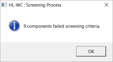
Click Inspect.
Once the screening is complete, a dialog will display the number of
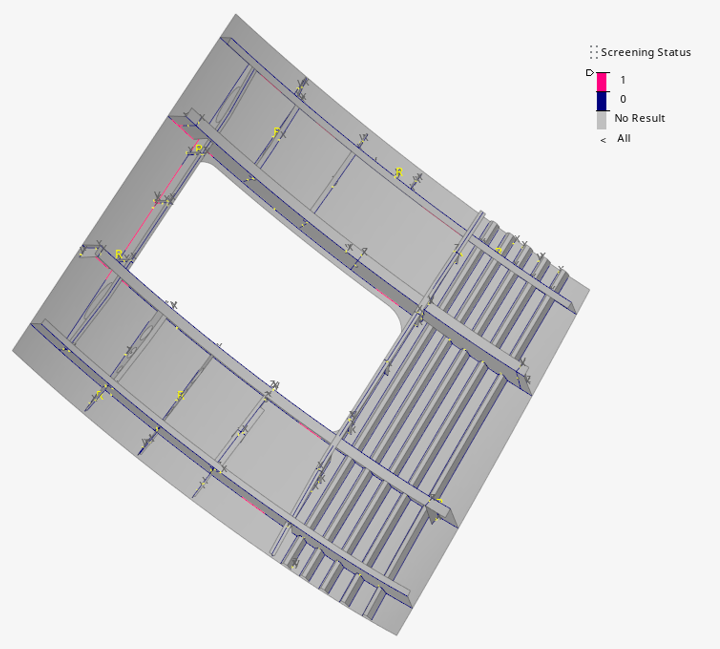
failed weld lines.Figure 15.
Click OK.
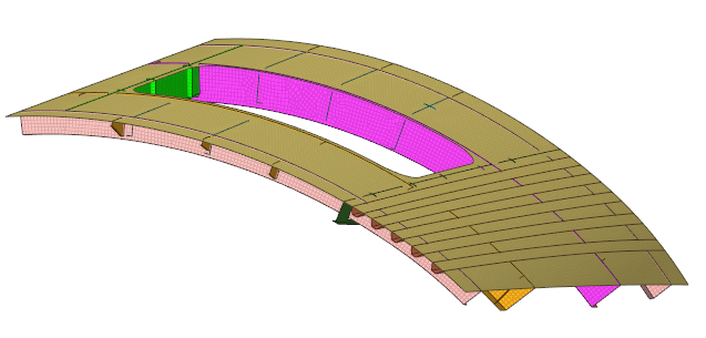
The legend on the right side of the modeling window
colors failed weld lines in pink.Figure 16.
Optional: Click in the
dialog to plot the ratio of the von Mises stress value of an element and the
threshold value you provided.
Exit the Inspect Browser dialog.
Define a Weld Specification
Click the Specifications tool.
Figure 17.
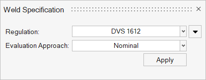
The Weld Specification dialog opens.
Select DVS 1612 from the Regulation drop-down
menu.
Figure 18.
Click Apply.
Parameters are applied to all the weld line
evaluation points.
Click OK.
Review Evaluation Points
Click the Points tool.
Figure 19.
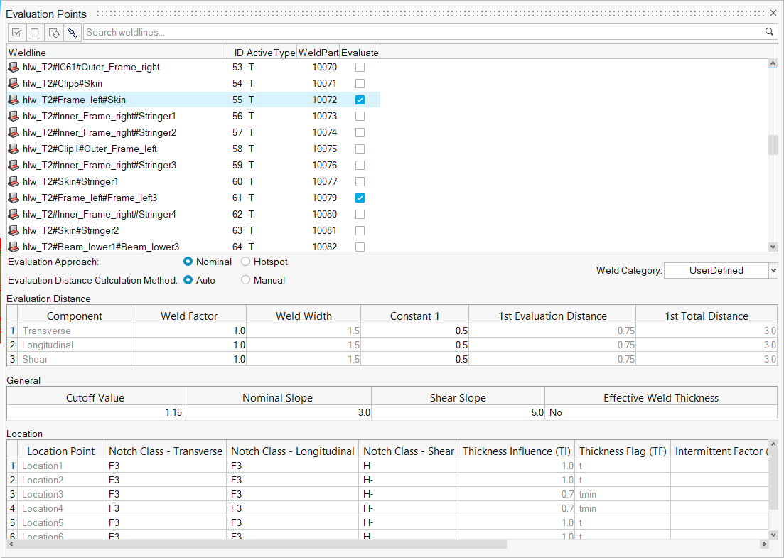
The Evaluation Points dialog opens.
Select hlw_T2#Frame_left#Skin from the weld line list.
Note: The Evaluate checkbox should be activated. Any weld lines that are marked as critical in the screening
process are automatically selected in the Evaluation
Points dialog.
Review the classification parameters.
The classification parameters for each weld vary depending on the weld type
and the weld regulation selected.Figure 20.
Review other weld lines at your own discretion then exit
the dialog.
Evaluate and View Results
From the Evaluate tool group, click the
Run Analysis tool.
Figure 21. By default, an event with all subcases is created. The created event will
compare the subcases placed within an event to create the maximum range.
The Evaluate Welds dialog opens.
Optional: Enter a name for the run.
Optional: Edit the default event or create a new subcase through the LoadMap
context.
Figure 22.
Click Evaluate.
A summary of the run appears.
Click OK to close the dialog.
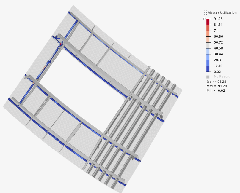
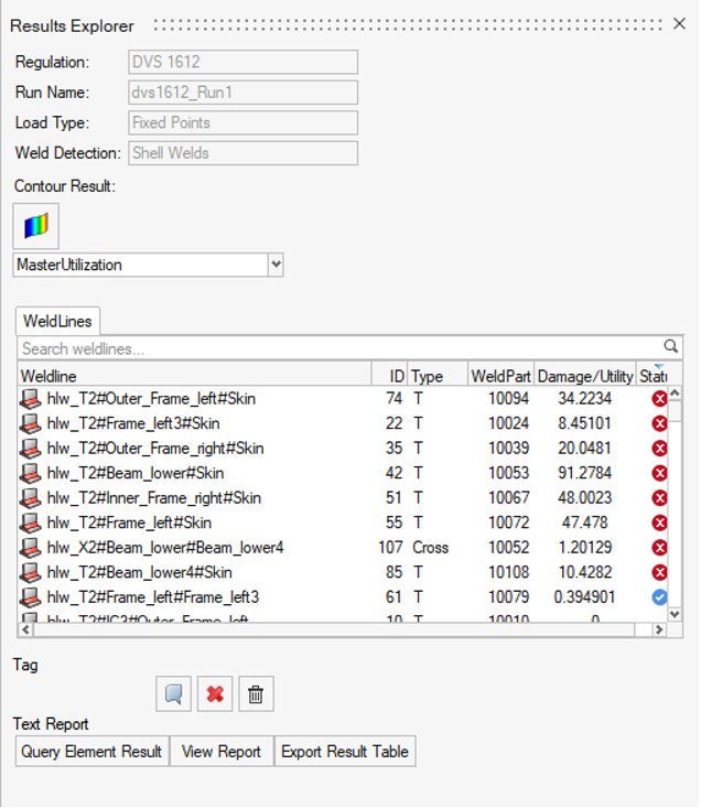
The Results Explorer opens and the model is
contoured.Figure 23.
In the Results Explorer, select
Location_4 from the first drop-down menu and
Max_Utilization from the second drop-down menu, then
click .
Figure 24.
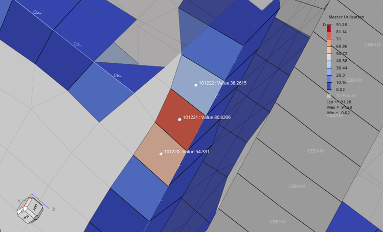
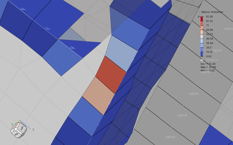
Zoom in on the model to view areas of interest.
Figure 25.
Add tags to elements.
Under the Tag field of the Results Explorer,
click .
Select elements to tag.
Click on the
entity selector.
The selected elements are tagged with IDs and utilization
values.Figure 26.

 The Mark Weld dialog opens.
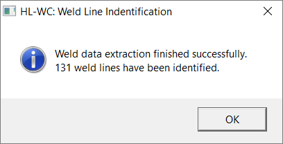
 .
An entity selector appears.
.
An entity selector appears.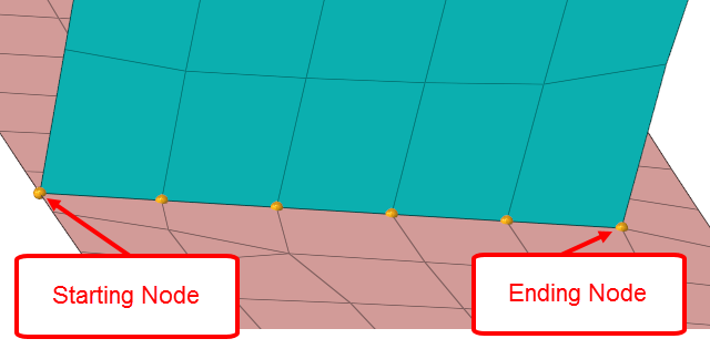
 on the entity selector.
The newly created weld line is displayed in the Mark Weld dialog.
on the entity selector.
The newly created weld line is displayed in the Mark Weld dialog.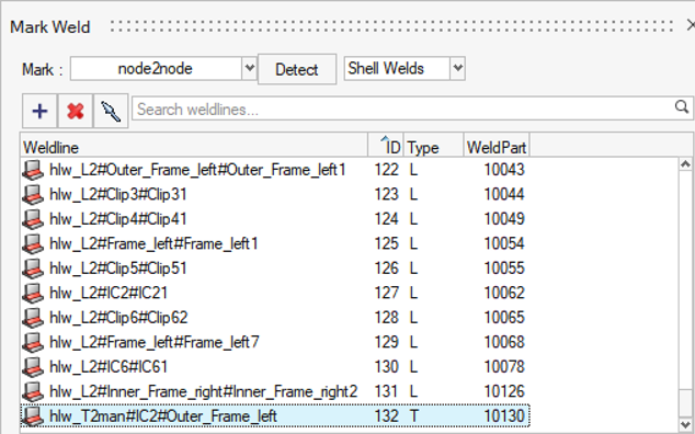
 The Inspect Browser dialog opens.
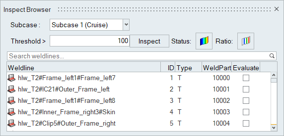
 in the
dialog to plot the ratio of the von Mises stress value of an element and the
threshold value you provided.
in the
dialog to plot the ratio of the von Mises stress value of an element and the
threshold value you provided.


 The Evaluate Welds dialog opens.
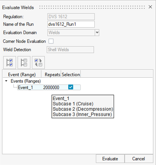
 .
.
 .
.