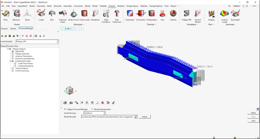
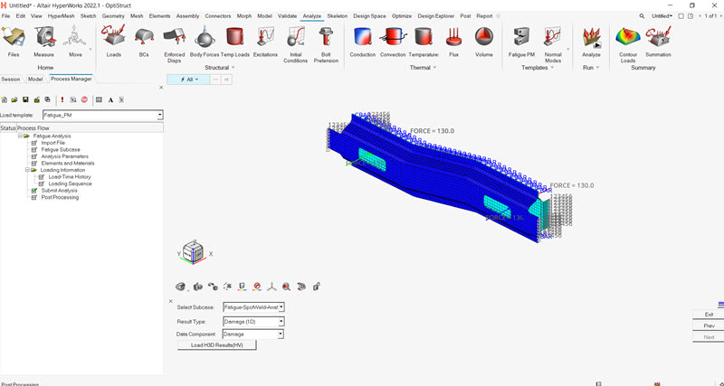
Make sure the task Import File is selected in the
Fatigue Analysis tree.
For the Model file type, select OptiStruct.
Click the Open model file icon .
A Select File browser window opens.
Select the Spotweld_CbarNugget.fem file you saved to
your working directory and click Open.
Click Import.
This loads the control arm model. It includes a whole definition of two
static subcases, elements sets, and material static properties,
etc.
Click Apply.
This guides you to the next task Fatigue Subcase of the Fatigue Analysis
tree.図 3. Import a Finite Element Model file
モデルのセットアップ
Create a Fatigue Subcase
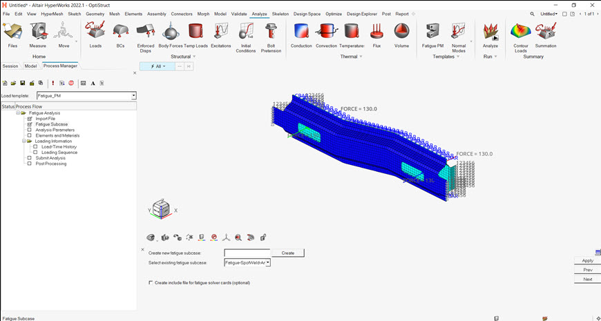
Make sure the task Fatigue Subcase is selected in the Fatigue Analysis
tree.
In the Create new fatigue subcase field, enter Fatigue-SpotWeld-Analysis.
Click Create.
For the Select existing fatigue subcase field, select the newly created fatigue
subcase Fatigue-SpotWeld-Analysis.
Fatigue-SpotWeld-Analysis is selected as the active fatigue
subcase. Definitions in the following processes (analysis parameters, fatigue
elements and properties, loading sequences, etc.) will be for this
subcase.
Optionally, you can choose to create all fatigue solver cards (such as
FATPARM, FATDEF,
FATEVNT, PFAT etc. that are created in
subsequent steps) in a separate include file. For this, you should select the
check box Create include file for fatigue solver cards
(optional).
Click Apply.
This saves the current definitions and guides you to the next task
Analysis Parameters of the Fatigue Analysis tree.図 4. Create and Select Active Fatigue Subcase to Process
Apply Fatigue Analysis Parameters
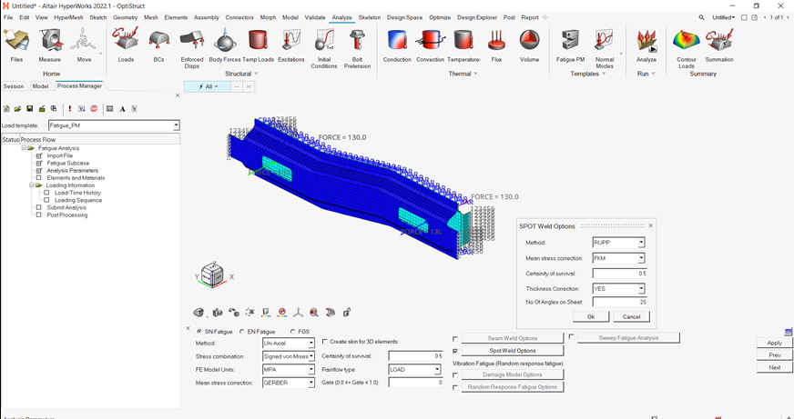
Make sure the task Analysis Parameters is selected in the Fatigue Analysis
tree.
Select the following options:
Analysis type
S-N
Stress combination method
Signed von Mises
FEA model unit
MPA
Mean stress correction
GERBER
Rainflow type
LOAD
Enter the following values:
Certainty of survival
0.5
Gate
0.0
Check the box for Spot Weld Options.
Select the follow options from the dialog.
METHOD
RUPP
Mean Stress Correction
FKM
Certainty of survival
0.5
THCKCORR
YES
NANGLE
20
Click Apply.
This saves the current definitions and guides you to the next task
Elements and Materials of the Fatigue Analysis tree. For details, consult the
Altair HyperWorks2024 help.図 5. Fatigue Analysis Parameters Definition
疲労要素と材料の追加
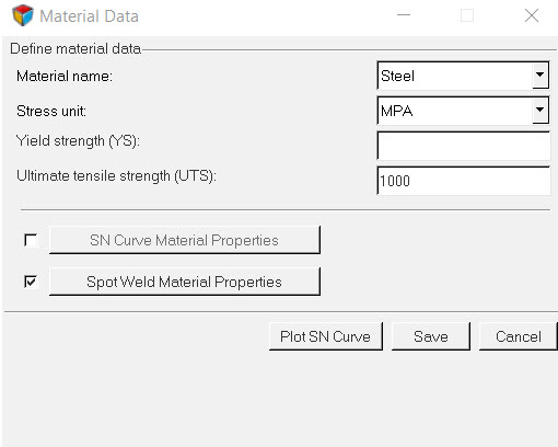
Fatigue AnalysisツリーでタスクElements and Materialsが選択されていることを確認します。
Add Materialをクリックします。
Material Dataウィンドウが開きます。
Material名にSteelを選択します。
Stress unitがMPAにセットされていることを確認します。
Ultimate tensile strength (UTS)に、1000と入力します。
Spot Weld Material
Propertiesをアクティブ化し、Spot Weld Material
Propertiesをクリックします。
図 6. 材料データ定義
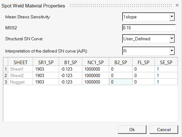
Mean Stress Sensitivity、MSS2、Structural SN Curve、およびBending SNとMembrane SNのカーブ材料値に、材料値を入力します。
図 7. Spot Weld Material Propertiesダイアログ
OKをクリックします。
Saveをクリックします。
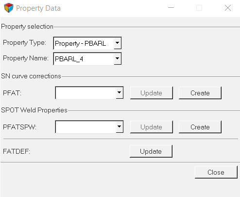
Add Propertyをクリックします。
図 8. Property Dataダイアログ
Property TypeにProperty -
PBARLを選択します。
Property NameにPBARL_4を選択します。
Closeをクリックし、選択された要素へのSNデータ定義を保存します。
Define PFATSPW Property
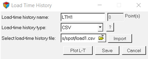
This saves the current definitions and guides you to the next task Load-Time History
of the Fatigue Analysis tree.
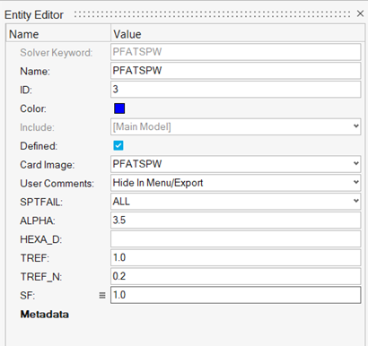
Click Create button next to PFATSMW.
A PFATSMW Entity Editor dialog opens.
For Name, enter PFATSPW.
For Card Image, select PFATSPW.
Set SPTFAIL to All.
Set ALPHA to 3.5.
Set TREF to 1.0.
Set TREF_N to 0.2.
図 9. PFATSPW
Dialog
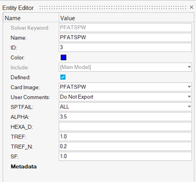
Set SF to 1.0.
Click Close.
Update FATDEF Load Collector
Click on Update button next to FATDEF.
A FATDEF Entity Editor opens.
Make sure the PTYPE and
PBARL options are checked.
Make sure the PID field under PBARL is pointing to
PBARL_4 and PFATSPWID is pointing to
PFATSPW card.
図 10.
Click Close to close the FATDEF dialog.
Click Close button to close the Property Data
dialog.

 .
A Select File browser window opens.
.
A Select File browser window opens.