Stamping
A stamping constraint should be used when the manufacturing process calls for stamping rather than casting.
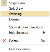
A stamping constraint can be applied from the part context menu.
This type of constraint should be used when the manufacturing process calls for stamping rather than casting. When you run an optimization on a design space with a stamping constraint applied, the solver returns a result with uniform thickness while avoiding negative draft angles and internal voids.
When applying a stamping constraint, you may also specify the No Hole option in the microdialog to eliminate internal voids. Stamping constraints are valid for optimization but not analysis.
Apply a Stamping Constraint
Click on a design space and use the context menu to apply a stamping constraint.
- Right-click on a design space in the modeling window or in the Model Browser.
-
Choose from the context menu.
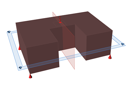
A blue rectangle appears on the selected design space, indicating the active plane for the stamping constraint
- Left-click to exit the context menu.
-
Double-click on the stamping constraint in the modeling window to enter editing
mode.
A microdialog appears, along with a set of three orthogonal planes. The active plane is shown in blue.
- Select a plane to orient the stamping direction.
- Right-click and mouse through the check mark to exit, or double-right-click.
- Click the
 icon on the microdialog to eliminate internal
voids in the optimized part.
icon on the microdialog to eliminate internal
voids in the optimized part.
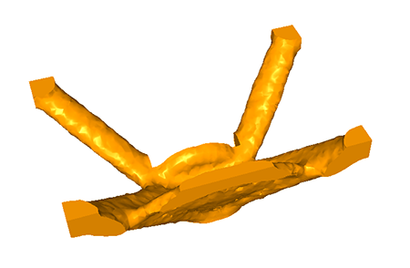
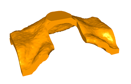
Stamping Examples