Create evenly spaced or biased nodes by interpolating between existing nodes in
space, on a surface, or on a curved or straight line.
From the Topology ribbon, click the Create Points/Nodes tool.
Figure 1.
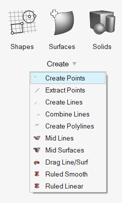
From the Geometry ribbon, click the arrow next to the
Create tool set, then select
Create Points.
Figure 2.
From the drop-down menu on the guide bar, select
Interpolate Nodes.
From the second drop-down menu on the guide bar, select
from the following:
Option
Description
Nodes
Select at least two nodes to interpolate nodes between.
Note: Input nodes are specified as a node
list, with each node considered as a pair with the next node
in the list.
In the Number of nodes field, enter the number of nodes to
create on a straight line between each selected node pair.
Select a bias style: linear,
exponential, or bell
curve.
In the Bias intensity field, enter a value.
Note: Nodes are created in 3D space, and not
merely on geometry.
Lines
Select lines and at least two nodes to interpolate nodes
between.
Use the Node List selector to select existing nodes.
Input
nodes are specified as a node list, with each node
considered as a pair with the next node in the list.
Note: Input nodes are not required to
lie on the selected line, as all input nodes are first
projected onto the line.
In the Number of nodes field, enter the number of nodes to
create between each selected node pair.
Select a Bias style: linear,
exponential, or bell
curve.
In the Bias intensity field, enter a value.
Locations
Select at least two locations to interpolate nodes between.
In the Number of nodes field, enter the number of nodes to
create between each selected node pair.
Select a Bias style: linear,
exponential, or bell
curve.
In the Bias intensity field, enter a value.
Surfaces
Select surfaces and at least two nodes to interpolate nodes
between.
Use the Node List selector to select existing nodes.
Input
nodes are specified as a node list, with each node
considered as a pair with the next node in the list.
Note: The nodes are not required to lie
on the selected surface, as all input nodes are first
projected onto the surface.
In the Number of nodes field, enter the number of nodes to
create between each selected node pair.
Select a Bias style: linear,
exponential, or bell
curve.
In the Bias intensity field, enter a value.
When complete, from the guide bar, click one of the
following:
- Apply and stay in the tool.
- Apply and close the tool.
- Exit the tool without applying.
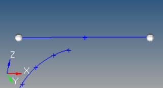
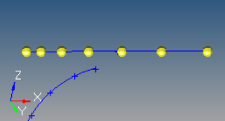
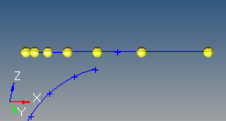
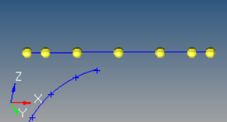
The following figures illustrate the effect of adding five nodes between the end
nodes of a line using the different bias styles with a bias intensity of 5.0.
Figure 3. Original Line Figure 4. Linear Bias Figure 5. Exponential Bias Figure 6. Bellcurve Bias
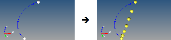
Nodes are created in 3D space, and not merely on geometry as shown in the previous
images.Figure 7.
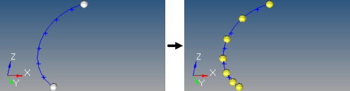
The following figure illustrates nodes interpolated along a curved line. Five nodes
created between two input nodes along a curved line, using linear biasing.Figure 8.
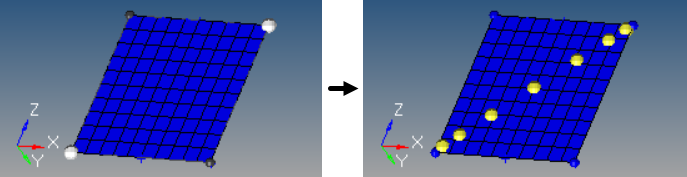
The following figure illustrates nodes interpolated on a surface. The highlighted
opposing corner nodes have seven interpolated nodes created between them, using
Bellcurve biasing.Figure 9.


 - Apply and stay in the tool.
 - Apply and close the tool.
 - Exit the tool without applying.