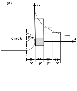
The crack tip geometry and averaged stresses over individual
elementary material blocks
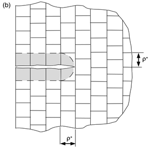
Figure 2.
A crack and the discrete elementary material blocks
The idealized crack tip geometry and the discrete structure of a material 1.
The following assumptions were applied in this method:
The material is assumed to be composed of identical elementary material
blocks of a finite dimension in Figure 1 and Figure 2
The fatigue crack can be analyzed as a sharp notch with a finite tip radius
of dimension
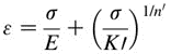
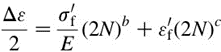
The material cyclic and fatigue properties used in the crack growth model
are obtained from the Ramberg-Osgood cyclic stress strain curve Figure 3. and the strain-life(eN) fatigue curveFigure 4.
The number of cycles to failure of the first elementary material
block at the crack tip can be determined from the strain-life fatigue curve
(Figure 4) by accounting for the stress-strain history at the crack tip and by
using the Smith-Watson-Topper (SWT) fatigue damage parameter and Miner rule.
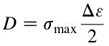
Once accumulated damage reaches 1, is a summation of life () of found cycles.Figure 5.
The fatigue crack growth rate can be determined as the average fatigue crack
propagation rate over the elementary material block of the size .Figure 6.
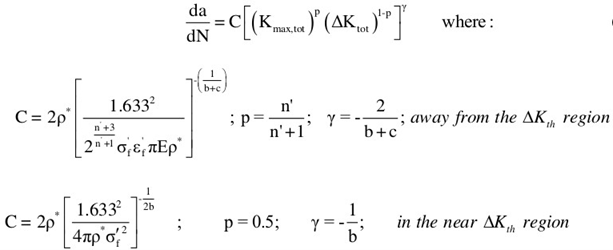
With the above assumptions and average linear stress over the elementary block with
the size , the following crack growth equations can be derived
to calculate crack growth 1:Figure 7.
Where,
Total maximum stress intensity factor
Total stress intensity range
Threshold stress range
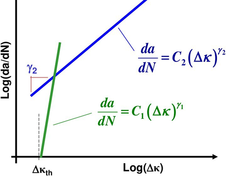
Figure 8.
Piece-wise linear crack growth equation where total driving force .