
RD-V: 0020 Cantilever Beam
Deflection of a cantilever beam modeled with different meshes and different element formulations.
The subject of this study is to analyze the quality of Radioss quasi-linear simulation using a simple use case. This should give an overview about the trade-off between quality and performance with respect to different modeling techniques. This example deals with the use of the Radioss nonlinear solver.
Based on a well-known small example from literature, the set-up of a simple Radioss input deck for a linear-elastic application will be shown: the cantilever-beam.
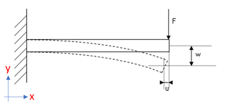
The beam is clamped at one end, and loaded with a concentrated force on the other end. The maximum vertical deflection is used for results comparison. This problem is well understood, and results can be easily compared with an analytical solution.
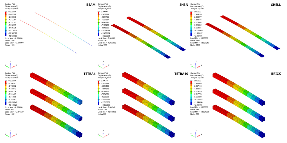
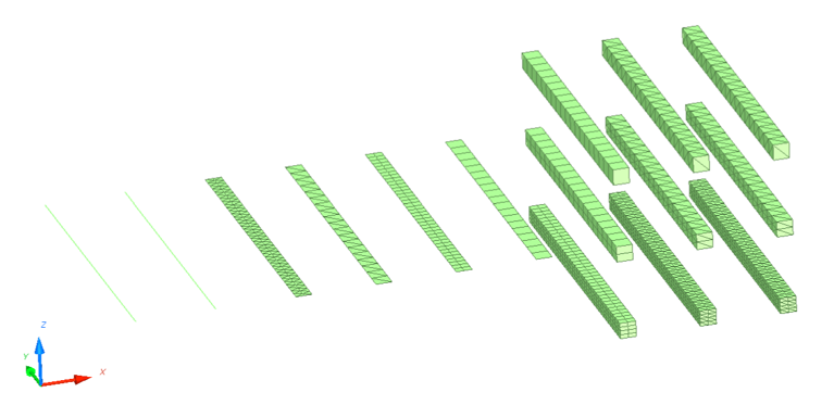
In this example, different mesh techniques are compared: beams, 3 and 4 noded shells, hexahedral elements and tetrahedral (tetra4 and tetra10) elements, as well as different element sizes.
The results are extracted and compared between each other with respect to their mesh size and element formulation. As output, the maximum vertical deflection, number of cycles, calculation time, element stress, and overall error are used. The maximum vertical deflection is compared to the theoretical value.
Options and Keywords Used
- /MAT/LAW1 (ELAST)
- /PROP/TYPE1 (SHELL)
- /PROP/TYPE3 (BEAM)
- /PROP/TYPE14 (SOLID)
- /TETRA4
- /TETRA10
- /BEAM
- /BRICK
- /SHELL
- /SH3N
- /CLOAD
- /FUNCT_SMOOTH
- Mesh density
Input Files
Model Description
This example's purpose is to compare different modeling methods for a simple cantilever beam in terms of quality and performance.
- Initial density
- 7.8 x 10⁻⁹ [Mg/mm3]
- Young's modulus
- 210000 [MPa]
- Poisson ratio
- 0.3
- Thickness
- 10 [mm]
- Length
- 190 [mm]
- Width
- 10 [mm]
- Load case
- Fx = 0
For the linear problem, the analytical solution gives:
- Force
- Length of the beam
- Young's modulus
- Moment of inertia
The theoretical deflection is determined to w = 13.07 mm.
Simulation Iterations
- /BEAM
- /SH3N
- /SHELL
- /BRICK
- /TETRA4
- /TETRA10
- Cross section
- 100 mm2
- Moment of Inertia (bending)
- 833.33333 mm4
- Moment of Inertia (torsion)
- 1666.66666 mm4
For shell elements (/PROP/TYPE1 (SHELL)), two element formulations QBAT-shell (Ishell = 12) and QEPH-shell (Ishell = 24) are used.
For brick elements (/PROP/TYPE14 (SOLID)), the solid formulations Isolid = 14, 17, 18 and 24 are investigated.
For Tetra4 elements, the formulations Itetra4 = 0, 1, 3 are used, and for Tetra10 elements, the formulations Itetra10 = 0, 2 are used.
Even though the displacement is small and a linear solver could be used, the nonlinear explicit and implicit solvers are used. The nonlinear implicit solver can be activated by using /IMPL/NONLIN.
Results
The tables below provide an overview about maximum deflection in Z-direction compared to the theoretical result. The results are compared between each other with respect to their mesh size, total number of cycles, energy error and difference of deflection compared to the theoretical value. The explicit CPU costs are normalized with respect to the QEPH shell simulation running on a single CPU and should be considered approximate. For Implicit calculation the CPU costs are similar for all element types. The displacement results in the table are reported at the main node of the rigid body attached to the end of the beam where the force is applied.
Explicit Solver
| Element | Mesh Size [mm] | Element Formulation | Maximum Deflection in Z-Direction [mm] | CPU Cost Factor (vs QEPH Shells) | Total Number of Cycles | Difference to Theoretical value [%] |
|---|---|---|---|---|---|---|
| BEAM | 10 | BEAMN3 | 13.03 | 0.7 | 142451 | 0.3 |
| 5 | 13.03 | 0.3 | ||||
| SH3N | 10 | Ish3n=0,2 | 12.919 | 1.7 | 245758 | 1.2 |
| 5 | 12.981 | 0.7 | ||||
| SH3N | 10 | Ish3n=30 | 12.903 | 3.5 | 450006 | 1.3 |
| 5 | 12.923 | 1.1 | ||||
| QBAT | 10 | Ishell = 12 BATOZ |
12.885 | 1.5 | 139698 | 1.4 |
| 5 | 12.946 | 0.9 | ||||
| QEPH | 10 | Ishell = 24 QEPH |
12.975 | 1.0 | 137169 | 0.7 |
| 5 | 12.997 | 0.6 |
| Element | Mesh Size [mm] | Element Formulation | Maximum Deflection in Z-Direction [mm] | CPU Cost Factor (vs QEPH Shells) | Total Number of Cycles | Difference to Theoretical value [%] |
|---|---|---|---|---|---|---|
| TETRA4 | 10 | Itetra4 = 0 | 3.633 | 3.6 | 344287 | 72.2 |
| 5 | 5.245 | 59.9 | ||||
| 2.5 | 9.171 | 29.8 | ||||
| TETRA4 | 10 | Itetra4 = 1 | 10.324 | 7.6 | 344278 | 21.0 |
| 5 | 11.231 | 14.1 | ||||
| 2.5 | 12.452 | 4.7 | ||||
| TETRA4 | 10 | Itetra4 = 3 | 5.259 | 5.2 | 344256 | 59.8 |
| 5 | 6.003 | 54.1 | ||||
| 2.5 | 9.743 | 25.5 | ||||
| TETRA10 | 10 | Itetra10 = 0 | 13.341 | 30.2 | 1301765 | 2.1 |
| 5 | 13.824 | 5.8 | ||||
| 2.5 | 13.613 | 4.2 | ||||
| TETRA10 | 10 | Itetra10 = 2 | 13.341 | 12.7 | 478818 | 2.3 |
| 5 | 13.824 | 5.8 | ||||
| 2.5 | 13.613 | 4.2 |
| Element | Mesh Size [mm] | Element Formulation | Maximum Deflection in Z-Direction [mm] | CPU Cost Factor (vs QEPH Shells) | Total Number of Cycles | Difference to Theoretical value [%] |
|---|---|---|---|---|---|---|
| BRICK | 10 | Isolid = 14 | 12.964 | 5.5 | 281572 | 0.8 |
| 5 | 12.890 | 1.4 | ||||
| 2.5 | 12.939 | 1.0 | ||||
| BRICK | 10 | Isolid = 17 | 15.682 | 4.0 | 281584 | 20.0 |
| 5 | 9.910 | 24.2 | ||||
| 2.5 | 11.985 | 8.3 | ||||
| BRICK | 10 | Isolid = 18 | 12.964 | 5.6 | 281572 | 0.8 |
| 5 | 12.890 | 1.4 | ||||
| 2.5 | 12.939 | 1.0 | ||||
| BRICK | 10 | Isolid = 24 HEPH |
12.966 | 2.6 | 281558 | 0.8 |
| 5 | 12.890 | 1.4 | ||||
| 2.5 | 12.939 | 1.0 |
Implicit Solver
| Element | Mesh Size [mm] | Element Formulation | Maximum Deflection in Z-Direction [mm] | Total Number of Cycles | Difference to Theoretical value [%] |
|---|---|---|---|---|---|
| BEAM | 10 | BEAMN3 | 13.032 | 12 | 0.3 |
| 5 | 13.032 | 0.3 | |||
| SH3N | 10 | Ish3n=0 | 12.909 | 15 | 1.2 |
| 5 | 12.968 | 0.8 | |||
| SHELL | 10 |
Ishell = 12 BATOZ |
12.951 | 15 | 0.9 |
| 5 | 12.975 | 0.7 | |||
| SHELL | 10 | Ishell = 24 QEPH |
12.958 | 13 | 0.9 |
| 5 | 12.976 | 0.7 |
| Element | Mesh Size [mm] | Element Formulation | Maximum Deflection in Z-Direction [mm] | Total Number of Cycles | Difference to Theoretical value [%] |
|---|---|---|---|---|---|
| TETRA4 | 10 | Itetra4 = 0 | 3.633 | 12 | 72.2 |
| 5 | 5.244 | 59.9 | |||
| 2.5 | 9.172 | 29.8 | |||
| TETRA4 | 10 | Itetra4 = 3 | 5.26 | 12 | 59.8 |
| 5 | 6.00 | 54.1 | |||
| 2.5 | 9.75 | 25.4 | |||
| TETRA10 | 10 | Itetra10 = 0 | 13.336 | 16 | 2.0 |
| 5 | 13.819 | 5.7 | |||
| 2.5 | 13.608 | 4.1 |
| Element | Mesh Size [mm] | Element Formulation | Maximum Deflection in Z-Direction [mm] | Total Number of Cycles | Difference to Theoretical value [%] |
|---|---|---|---|---|---|
| BRICK | 10 | Isolid = 14 | 12.965 | 15 | 0.8 |
| 5 | 12.890 | 1.4 | |||
| 2.5 | 12.939 | 1.0 | |||
| BRICK | 10 | Isolid = 17 | 15.673 | 16 | 19.9 |
| 5 | 9.908 | 24.2 | |||
| 2.5 | 11.981 | 8.3 | |||
| BRICK | 10 | Isolid = 18 | 12.964 | 18 | 0.8 |
| 5 | 12.890 | 1.4 | |||
| 2.5 | 12.939 | 1.0 | |||
| BRICK | 10 | Isolid = 24 HEPH |
12.966 | 15 | 0.8 |
| 5 | 12.890 | 1.4 | |||
| 2.5 | 12.939 | 1.0 |
Conclusion
- Explicit Solver
- Beam
- BEAM3N returns good results for the coarse and the fine mesh. The difference of deflection compared to the theoretical value is about 0.2%.
- Shells
- When the beam is modeled with 4 node shell elements, QEPH (Ishell = 24) is the best choice of element formulation. Compared to QBAT (Ishell = 12), it returns similar results regarding mesh size, energy error, with very good precision versus cost.
- Tetras
- Itetra4 = 0 or 3 elements are too stiff and do not return reasonable results, unless a fine mesh is used. Although, having a higher computational cost, the Itetra4 = 1 element formulation returns better results especially when a fine mesh is used.
- Bricks
- Hexa8 elements with Isolid = 24 element formulation return the best results regarding mesh size, and calculation time. They also have very good precision versus cost ratio. The difference of deflection compared to the theoretical value is about 1%. Compared to the other brick element formulations calculation time is about 2 – 2.5 lower. When used with nonlinear materials, Isolid = 24 requires 3 or more elements through the thickness. For 1 or 2 elements through the thickness, a fully-integrated element, like Isolid = 14 or 18 is recommended. The Isolid = 18 element automatically selects the best property settings depending on the material it is used with. The fully-integrated Isolid = 17 element suffers from shear locking which causes it to be too stiff and therefore not recommended.
- Implicit Solver
- Beam
- BEAM3N returns good results for the coarse and the fine mesh. The difference of deflection compared to the theoretical value is about 0.3%.
- Shells
- Shell elements with different element formulations return good results regarding mesh size and calculation time. The difference of deflection to the theoretical value is under 1%. The QEPH shell shows best performance versus precision ratio and is recommended.
- Tetras
- Tetra10 elements return good results in terms of quality compared to tetra4 elements, which are too stiff in their behavior. The difference of deflection compared to the theoretical value varies between 2 to 6% and depends on the mesh size. For Tetra4 elements, the deflection compared to the theoretical value is to low, but begins to converge with finer mesh size. The Itetra4 = 1 and Itetra10 = 2 element formulations are not supported in implicit analysis.
- Bricks
- Hexa8 elements with different element formulations return good results for the coarse and the fine mesh, except for element formulation Isolid = 17 which suffers from shear locking. The difference of deflection compared to the theoretical value is about 1%. The Hexa8 elements with Isolid = 24 show the best performance regarding precision of results and calculation time.