OS-T:5090 アルミ製フィンの熱最適化
本チュートリアルでは、アルミ製フィンの形状最適化を行います。
開始する前に、このチュートリアルで使用するファイルを作業ディレクトリにコピーします。
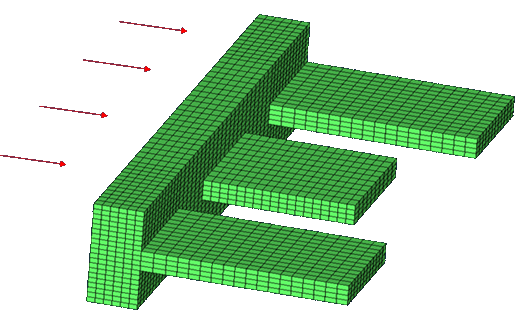
フィンのベースのパートは、q=8000 W/m2の一定熱流束を受けます。周囲の空気の温度は283 Kで、対応する熱伝導率はH = 40 W/m2 • Kです。熱伝達係数はK = 221 W/m • K。フィン内の温度分布は、熱伝達および熱伝導荷重ケースを解くことによって決定されます。図 1. モデルの概要
この最適化問題の設定は以下のとおりです;
- 目標
- ベース中央における温度の最小化
- 制約条件
- 体積 < 1.0e-5 m2
- 設計変数
- 形状設計変数
HyperMeshの起動とOptiStructユーザープロファイルの設定
-
HyperMeshを起動します。
User Profilesダイアログが現れます。
-
OptiStructを選択し、OKをクリックします。
これで、ユーザープロファイルが読み込まれます。ユーザープロファイルには、適切なテンプレート、マクロメニュー、インポートリーダーが含まれており、OptiStructモデルの生成に関連したもののみにHyperMeshの機能を絞っています。
モデルの読み込み
-
をクリックします。
Importタブがタブメニューに追加されます。
- File typeにOptiStructを選択します。
-
Filesアイコン
 を選択します。
Select OptiStruct Fileブラウザが開きます。
を選択します。
Select OptiStruct Fileブラウザが開きます。 - 自身の作業ディレクトリに保存したfins.femファイルを選択します。
- Openをクリックします。
- Import、続いてCloseをクリックし、Importタブを閉じます。
最適化のセットアップ
HyperMorphでの形状の作成
- Analysisページからパネルoptimizationをクリックします。
- HyperMorphパネルをクリックします。
- Freehandパネルをクリックします。
- move nodesサブパネルを選択します。
- movementオプションをtranslateにセットします。
-
移動距離を入力します。
フィンはX方向のみに拡張します。
- x=欄に0.03と入力します。
- y=欄に0.0と入力します。
- z= 欄に0.0と入力します。
-
moving nodesを選択します。
- moving nodesの下で、をクリックします。
- sh1_moveを選択し、selectをクリックします。
選択された移動節点がハイライト表示されます。 -
fixed nodesを選択します。
- fixed nodesの下で、をクリックします。
- sh1_fixを選択し、selectをクリックします。
選択された固定節点がハイライト表示されます。 -
affected elementsを選択します。
- affected elementsの下で、をクリックします。
- sh1_elemを選択し、selectをクリックします。
選択された要素がハイライト表示されます -
morphをクリックします。
フィンがX方向に拡張されます。
-
形状を保存します。
- save shapeサブパネルを選択します。
- name =欄にsh1と入力します。
- トグルをas handle perturbationsからas node perturbationsに切り替えます。
- saveをクリックします。
形状設計変数用のsh1が生成されます。 - undo allをクリックします。
- 上記の手順を繰り返し、オリジナルモデル上に形状sh2とsh3を作成します。対応する節点セット(sh2_move/fixとsh3_move/fix)および要素セット(sh2_elemとsh3_elem)は予め定義されています。
- returnを2回クリックし、Optimization panelに戻ります。
形状設計変数の作成
- shapeパネルをクリックします。
- desvarサブパネルを選択します。
- single desvarからmultiple desvarsに切り替えます。
- 形状セレクターを使用し、 sh1、sh2、およびsh3を選択します。
- initial value欄に0.0と入力します。
- lower bound欄に-1.0と入力します。
- Upper bound欄に2.0と入力します。
- createをクリックします。
- returnをクリックし、Optimization panelに進みます。
Create Optimization Responses
- From the Analysis page, click optimization.
- Click Responses.
-
Create the volume response, which defines the volume fraction of the design
space.
- In the responses= field, enter volume.
- Below response type, select volume.
- Set regional selection to total and no regionid.
- Click create.
-
Create the temperature response.
- In the response= field, enter temperature.
- Set the response type to temperature.
- Click , then enter 2450 in the id= field.
- Click create.
The temperature response at node 2450 is created. - Click return to go back to the Optimization panel.
Create Design Constraints
- Click the dconstraints panel.
- In the constraint= field, enter vol.
- Click response = and select volume.
- Check the box next to upper bound, then enter 1.0e-5.
- Click create.
- Click return to go back to the Optimization panel.
Define the Objective Function
- Click the objective panel.
- Verify that min is selected.
- Click response and select temperature.
- Using the loadsteps selector, select heat transfer subcase.
- Click create.
- Click return twice to exit the Optimization panel.
SHAPEカードの定義
- Analysisページからパネルcontrol cardsをクリックします。
- Card Imageダイアログで、SHAPEをクリックします。
- FORMATをH3Dに設定します。
- TYPEをALLに設定します。
- OPTIONをALLに設定します。
- returnを2回クリックし、メインメニューに戻ります。
Run the Optimization
- From the Analysis page, click OptiStruct.
- Click save as.
-
In the Save As dialog, specify location to write the
OptiStruct model file and enter
fins_opt for filename.
For OptiStruct input decks, .fem is the recommended extension.
-
Click Save.
The input file field displays the filename and location specified in the Save As dialog.
- Set the export options toggle to all.
- Set the run options toggle to optimization.
- Set the memory options toggle to memory default.
-
Click OptiStruct to run the optimization.
The following message appears in the window at the completion of the job:
OPTIMIZATION HAS CONVERGED.
FEASIBLE DESIGN (ALL CONSTRAINTS SATISFIED).
OptiStruct also reports error messages if any exist. The file fins_opt.out can be opened in a text editor to find details regarding any errors. This file is written to the same directory as the .fem file. - Click Close.
結果の表示
最適化された形状での温度のコンタープロットをHyperViewで確認する方法を以下に示します。
- OptiStructパネルで、HyperViewをクリックします。
- Load Resultsパネルで、Model欄とResults欄の両方にfins_opt_s1.h3dファイルを読み込みます。
-
Applyをクリックします。
解析および最適化結果の両方が含まれる.h3dファイルが読み込まれます。
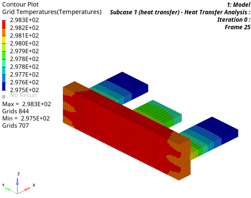
- Results Browserで、Iteration 0を選択します。
-
Resultsツールバーで
 をクリックし、Contour panelを開きます。
- Result typeをGrid Temperatures (s)に設定します。
-
Applyをクリックします。
アルミ製フィンの初期温度分布コンターが表示されます。
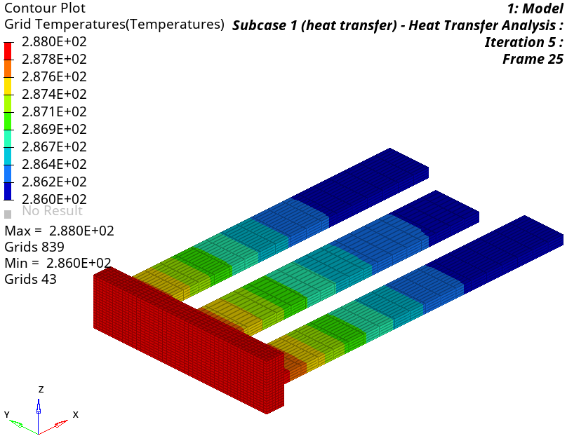
- Results Browserから、最終反復計算を選択します。
- Contour panelで、Result typeをShape Change (v)に設定してください。
-
Applyをクリックします。
最終反復計算における最適化された形状が読み込まれます。
- Result typeをGrid Temperatures (s)に設定します。
- Applyをクリックします。