Tutorial: Flexible Fastener Optimization
Run and compare the results of optimizations using rigid vs. flexible fasteners.
- Learn about the Huth-Schwarmann formulation for estimating fastener stiffness
- Run a topology optimization using rigid fasteners
- Enable connection stiffness in the Property Editor
- Run a topology optimization using flexible fasteners

Overview: Flexible Fastener Optimization
In Inspire, flexible fasteners can be created by using the Connection Stiffness property, which allows for better approximation of axial and shear stiffness in grounded fasteners, grounded joints, and cylindrical supports. Fastener flexibility and joint flexibility in general can have a significant effect on how loads are carried in and transferred through a structure.
Numerous methods exist to estimate fastener stiffness. Inspire has implemented the Huth-Schwarmann method, but also allows you to specify an independently calculated stiffness.
| Type | a | b |
|---|---|---|
| Bolted metallic | 2/3 | 3.0 |
| Riveted metallic | 2/5 | 2.2 |
| Bolted graphite/epoxy | 2/3 | 4.2 |
- Configuration:
- d = hole diameter
- Material:
- E = Young modulus
- Indices:
- 1 = Plate 1 (central one in double shear)
As an alternative to using the Huth-Schwarmann stiffness, user-defined stiffness values can also be applied. This is a more common approach when the parts can't be defined using a plate approximation. One example would be a cast aluminum automotive mount attached to a transmission housing. Rather than model the entire system, if only the mount is of interest, the connection stiffness can be approximated and used to give improved results.
Inspect the Connection Stiffness
- Press F7 to open the Demo Browser.
-
Double-click the rigid.stmod file to load it in the
modeling window.
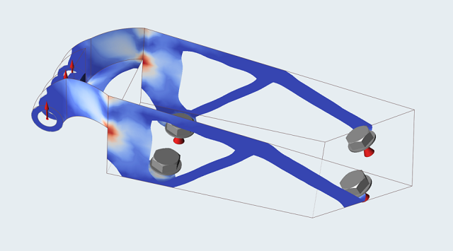
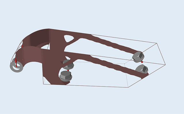
This is a surface model of the available design space of an actuator bracket. Note that all parts have a 2 mm thickness assigned, the design space has a symmetry plane, loads are applied, and the part is constrained using grounded bolts.
- Make sure the display units in the Unit System Selector are set to MPA (mm t N s).
- Press F3 to open the Property Editor.
-
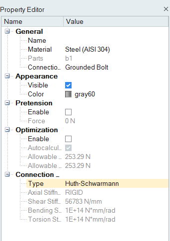
Select one of the grounded bolts and examine the Connection Stiffness field in
the Property Editor.
The Type is set to Default (rigid), but Huth-Schwarmann and User Defined are also available.
Run an Optimization Using Rigid Fasteners
-
Click Run Optimization
 on the Optimize icon on the Structure ribbon.

Tip: To find and open a tool, press Ctrl+F. For more information, see Find and Search for Tools. -
Set the options in the Run Optimization window as shown below:
- Select Topology for the Run type.
- Select Maximize Stiffness for the Objective.
- Set a Mass target of 30%.
- Enter a Minimum Thickness constraint of 3 mm.
- Click Run to perform the optimization.
- When the run is complete, double-click on the name of the run to view the results.
-
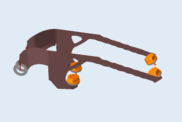
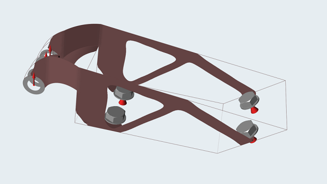
In the Shape Explorer, examine the results.
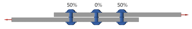
Note that the material connecting to the bolts farthest from the loading bosses is minimal. This is due to the bolts nearest the load being rigidly grounded, which limits the force being transmitted to the farthest bolts.
Analyze the Generated Shape
- Click the Analyze button on the Shape Explorer.
-
When the run is complete, double-click on the name of the run to view the
results.
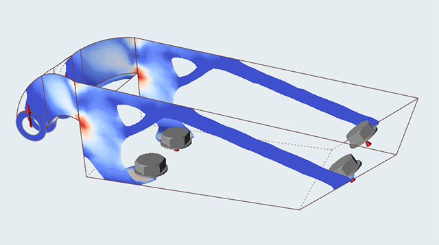
- If you examine the analysis results, it is clear the slender links to the remote bolts are relatively lightly loaded.
- Double-right-click to exit the Analysis Explorer.
Change the Connection Stiffness
- Either open the rigid_run.stmod file from the Demo Browser or continue with your model from the previous step.
-
Hold down the Ctrl key and select the four grounded
bolts in the modeling window or Model Browser.
-
In the Property Editor, change the Connection Stiffness
Type to Huth-Schwarmann.
The Shear Stiffness is calculated based on the part properties.
Rerun the Optimization Using Flexible Fasteners
-
Click Run Optimization
on the Optimize icon on the Structure ribbon.
- Re-run the optimization with the same settings used previously, and load the results.
-
Note the extra material connecting to the remote bolts as more load is now
being transferred to them.
-
Click the Analyze button on the Shape Explorer and when
the run is complete, load the results.
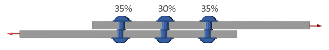
Notice with Huth-Schwarmann active a new material path has been added to account for the loading in the connection.