SS-T: 4150 Interference Fit using Align Contact Condition
- Purpose
- SimSolid performs meshless structural
analysis that works on full featured parts and assemblies, is tolerant of
geometric imperfections, and runs in seconds to minutes. In this tutorial,
you will do the following:
- Learn to use the align contact condition for removing any gap or penetration in the model where they are defined.
- Model Description
- The following model file is needed for this tutorial:
- Shaft_Assembly.ssp
-
Figure 1. 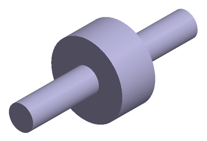
- The file has the following specifications:
- Material is set to Steel for all parts.
- Regular connection with bonded contact created.
- Solution settings set to Global+Local adaptation.
- The model exhibits initial penetration at the contact region as
shown in Figure 2.
Figure 2. 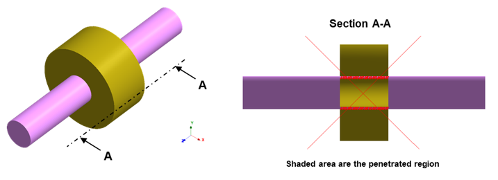
Open Project
-
On the main window toolbar, click Open Project
 .
.
- In the Open project file dialog, select Shaft_Assembly.ssp.
- Click OK.
Create Structural Linear Analysis
On the main window toolbar, click Structural Analysis  > Structural linear.
Create Immovable Support
-
In the Analysis Workbench, click Immovable
Support
 .
.
- In the dialog, verify the Faces radio button is selected.
-
In the modeling window, select the three faces
highlighted in orange.
Figure 3. 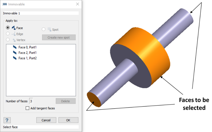
Create Contact Condition
-
Right-click on the part highlighted in orange, and select Review
part contact conditions.
Figure 4. 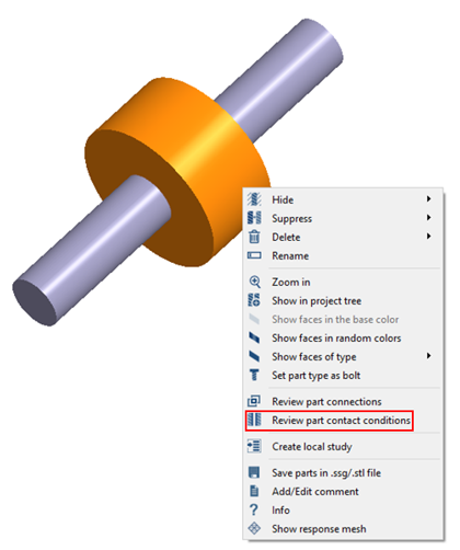
-
In the Review part contact condition dialog, ensure
Connection 1, bonded is highlighted and select
Edit.
The Custom Contact Condition dialog appears.
- In the dialog, select the Align radio button option.
- Click OK.
Solve Analysis
- In the Project Tree, ensure Structural 1 subcase is selected.
-
Click
 (Solve).
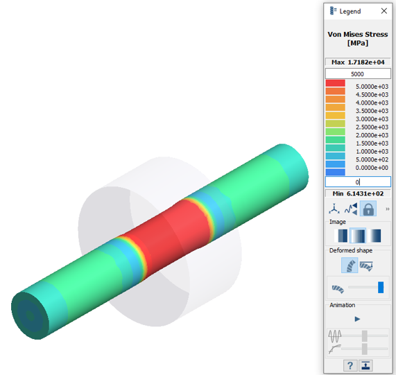
Review Results
- In the Project Tree, select the Results branch for Structural 1.
-
On the Analysis Workbench
toolbar, click
 (Results plot).
- Select the Displacement Magnitude plot.
-
In the Legend window, click
 (Show deformed
shape).
The modeling window updates to show the chosen results and display options.
(Show deformed
shape).
The modeling window updates to show the chosen results and display options.Figure 5. 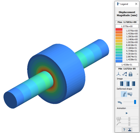
- Close the Legend window.
-
To isolate the part, select the part highlighted in orange and press
I on the keyboard.
Figure 6. 
-
On the Analysis Workbench
toolbar, click (Results plot).
- Select the plot.
- In the Legend dialog, set the minimum value to 0 MPa and the maximum value to 5000 MPa.