In a belt-pulley system, mechanical power is transmitted using a long, flexible belt
that wraps around rotating pulleys. This power transfer occurs through friction between the
belt and the pulley surface. The belt-pulley subsystem in MotionView enables rapid assembly of such a system with minimal
inputs, streamlining the process efficiently.
The belt-pulley system is assembled within a XZ plane of a
user defined reference marker, meaning the XZ plane of the marker aligns with the plane
formed by the pulley centers. Orienting the reference marker allows you to rotate the
belt-pulley system within a global system. Only in instances involving an NLFE belt
formulation, is it essential for the reference marker to remain aligned with the global
frame.
MotionView offers three types of belt-pulley systems:
Nonlinear Finite Element (NLFE) based – The belt is modeled as a series of
connected nonlinear finite element beams. Use this model if you are
interested in a high fidelity model that returns accurate belt stresses and
strains.
Note: These simulations can take a long
time.
Discretized rigid bodies – The belt is modeled as a series of rigid bodies
connected by bushings. Use this model if you are interested in the overall
motion of the belt-pulley system. These simulations are usually faster than
with NLFE or Substructured Flexbodies.
Substructured Flexbodies – This is an experimental feature available in
version 2024. The belt is modeled as a series of linear (CMS) flexible
bodies connected by fixed joints. This method offers a faster solution
compared to NLFE formulation and with a higher fidelity than discretized
rigid bodies formulation.
Formulation
NLFE
Discretized Rigid Bodies
Substructured Flexbodies
Speed
Very low
high
medium
Accuracy
high
low
medium
To create a belt-pulley system, follow the steps below:
From the Assembly ribbon, click the
Belt/Pulleys icon.
The Add a Belt-Pulley Subsystem dialog is
displayed.
Click the System collector and decide which system the
belt/pulley needs to be created in.
Specify a variable name and label for the belt/pulley.
By default, variable names of entities in MotionView follow a certain convention. For example, all belt/pulley entities have a
variable name starting with bp_. This is the recommended
convention to follow when building models in MotionView since it has many advantages in model editing
and model manipulation.
Select the type of Belt Formulation to represent the
belt using the drop-down menu.
If a reference frame other than global frame is to be used, select the
reference marker for pulley coordinates by double-clicking on the
Marker collector (located in the lower, left of the
dialog).
The belt-pulley system will be created such that the assembly lies within the
XZ plane of the reference frame.
By default, two pulleys are available. To add or delete a pulley, use the
right-click option on a row item indicating the pulley number.
Enter values for the X and Z coordinates of the pulley center in the reference
marker coordinate frame.
Enter a value for the radius of the belt and specify which side (inner or
outer) of the belt loop the pulley is positioned from the drop-down menu.
Specify the total number of pulleys to create.
As the pulley is added/deleted, this field will be automatically updated.
Enter values for the belt width and belt thickness in the text boxes on the
right side of the dialog.
A linear elastic Belt Rubber material is available in MotionView and is selected by default. To use a different
material, double click on the MaterialProperty collector
and select a different material from the list.
To create an NLFE belt formulation, complete the steps
below:
In the NLFE Belt Component area, the minimum number of NLFE beam
elements required to accurately represent the belt based on the
calculated belt profile is displayed in blue. By default, the minimum
number of required elements is used. To use more elements, deactivate
the Use minimum required option and specify the
number of NLFE beam elements to be created.
The effective diameter based on the calculated profile length of the
belt in the installed position is also displayed in blue. By default,
the dialog sets a value for the free diameter by a known amount of
offset from the installed free diameter. Deactivate the Use
calculated value option to provide a different value for
the belt free diameter.
Note: This number should be smaller than the installed belt diameter, so
that the belt is sufficiently pre-tensioned. The greater the
difference between the free diameter and the Installed diameter, the
more pretension is induced.
To create a Discretized rigid bodies belt formulation,
complete these steps:
In the Belt Stiffness Properties section of the dialog, enter tensile
stiffness and tensile damping values along the longitudinal direction of
the belt.
Enter bending stiffness and bending damping values along the bending
direction of the belt.
Enter a value for the pre-tension of the belt.
For the Belt Contact Properties (Impact) section, the parameters are
the same as that found in the Contact panel with Impact method. Refer to
the Contacts tool topic to learn more about each of the
parameters.
To create a Substructured Flex Bodies belt formulation,
complete these steps:
Enter a value for the Belt Preload (in force units).
For the Belt Contact Properties (Impact) section, the parameters are
the same as that found in the Contact panel with Impact method. Refer to
the Contacts tool topic to learn more about each of the
parameters.
Once all the above information is entered, click OK to
create the belt-pulley system and exit the dialog.
Note: In the case of Substructured Flex Bodies, the flex
body (CMS) is automatically created in the background for the belt
segment.
The NLFE belt-pulley system that is created has the following
architecture:
Entity
Description
Bodies
Rigid pulley bodies and an NLFE belt body consisting of a
series of nonlinear beam finite elements.
DataSet
A dataset where all editable values are stored. After the
creation of the belt-pulley system, you can change the free
diameter and width of the belt through this dataset.
Points
The points that define the uninstalled belt profile and
the pulley centers. These are hidden by default.
Graphics
The graphics for the pulleys.
Joints
Revolute joints between the pulley and attaching body. In
addition, there are joints that connect the pulley and belt
body that help in transmitting motion.
Markers
A reference marker to define the uninstalled
configuration of the belt (hidden by default).
Templates
Includes NLFE statements that are currently not supported
by MotionView. These include
GRIDS at the periphery of the pulley, LINE2 elements that
model contact between belt GRID and pulley GRID, and CONN1
elements that restrain the belt with the pulley along normal
of the belt-pulley plane.
The discretized rigid bodies belt-pulley has the following architecture:
Entity
Description
Bodies
Rigid pulley bodies and a belt body consisting of a
series of connected rigid bodies is created.
DataSet
A dataset where all editable values are stored. After the
creation of the belt-pulley system, you can change the free
diameter and width of the belt through this dataset.
Points
The points that define the belt profile and the pulley
centers. These are hidden by default.
Graphics
The graphics for the pulleys and belt.
Joints
Revolute joints between pulley and attaching body. In
addition there are joints that connect the pulley and belt
that hold the belt in the system plane.
Markers
A reference marker to define the uninstalled
configuration of the belt (hidden by default).
Templates
Includes MotionSolve command
statements to hide the graphics used in contact.
The Substructured Flex Bodies belt-pulley has the following
architecture:
Entity
Description
Bodies
Rigid pulley bodies and a belt body consisting of a
series of connected rigid bodies is created.
DataSet
A dataset for contact properties.
Points
The points that define the belt profile and the pulley
centers. These are hidden by default.
Deformable Curve
A deformable curve running through markers on the
flexible bodies at the belt profile points.
Graphics
The graphics for the pulleys.
Joints
Revolute joints between pulley and attaching body. Fixed
joints between belt flexible bodies. In addition, there are
joints that connect the pulley and belt that hold the belt
in the system plane.
Markers
A reference marker to define the uninstalled
configuration of the belt (hidden by default). Markers on
flexible bodies used in Deformable Curve.
Solver Arrays
Solver arrays that list the modal IC arrays for the
flexible bodies.
Templates
MotionSolve statements set
the modal IC arrays on the flexbodies and Deformable Curve
contact definition.
Tip:
Select Show additional parameters to specify variable
names and labels for the points that are to be created.
As the pulley X, Z, radii, and the belt side parameters are set, the preview
image shows the belt-pulley system configuration. The line joining the
pulleys tangentially represents the belt. For any incompatible information
(for example, overlapping locations of the pulleys, distance between two
pulley centers smaller than the summation of their radii) the belt line will
not be visible. Cross belt and out of plane pulley configurations are not
supported.
To return to default settings, click Reset to
Defaults.
Edit a Belt-Pulley System
Change the Pulley Mount Bodies
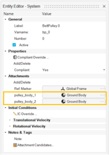
The pulleys, by default, are connected to ground body via revolute joints. To change
any of these attachments to a different body, select the BeltPulley system in the
Model Browser and change the
pulley_body_n Body attachment in the Attachments section of
the Entity Editor, as shown below:Figure 1.
Change the Belt Material (for NLFE belt and Discretized rigid bodies
only)
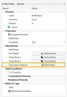
To change the material of the belt (for NLFE belt and Discretized rigid bodies only),
select the BeltPulley system in the Model Browser and change the
MaterialProperty attachment (Belt Graphic Material) to the belt-pulley system in the
Attachments section of the Entity Editor: Figure 2.
Note: Belt material cannot be changed for Substructured
Flex Bodies based formulation after the system is created.
Change the Pulley Material
The pulley material can be changed by:
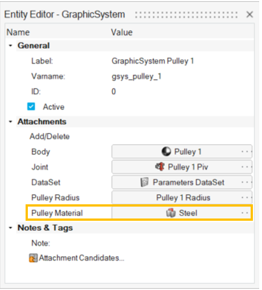
For NLFE Belt and Discretized rigid bodies, select the graphic system of the
pulley and change the material attachment in the Attachments section of the
Entity Editor: Figure 3.
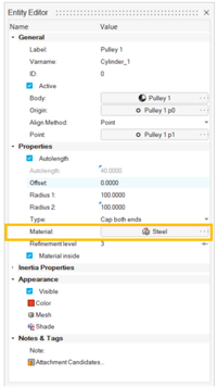
For Substructured Flex Bodies select the Pulley graphic in the Model Browser and change the Material under the Properties
section of the Entity Editor:Figure 4.
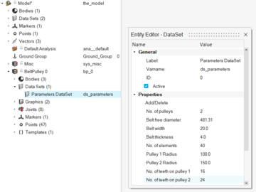
Change the Belt Parameters (for NLFE belt and Discretized rigid bodies
only)
Belt parameters can be changed through the dataset Parameters DataSet available
within the belt-pulley system.
The parameters that are active can be changed, while those that cannot be changed are
grayed out.
Figure 5.
Note: Belt parameters cannot be changed for Substructured Flex
Bodies based formulation after the system is created.
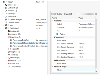
Change Stiffness Parameters for Discretized Rigid Bodies
In the case of a discretized rigid bodies belt, the stiffness parameter and belt
tension can be changed using the dataset Parameters Stiffness DataSet:Figure 6.
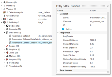
Change Contact Parameters for Discretized Rigid Bodies and Substructured Flex
Bodies
In the case of a discretized rigid bodies or Substructured Flex Bodies belt, the
parameters for contact between the belt and the pulleys can be changed through the
dataset Parameters Contact DataSet and ds_contact respectively.Figure 7.