Bus Rollover
Use the Bus Rollover tool for the automatic recognition of the unstable position of the bus, the automatic recognition of the impact position of the bus, and the automatic creation of loadcase for impact simulation.
The input model should be fully pre-defined including the bus, the survival space (if existing), the platform, all required contact definitions and control cards. The ground (impact surface) is a rigid wall or is a rigid Part and can be pre-defined or automatically created by the tool.
-
From the Safety ribbon, click the Bus
Rollover tool.
Figure 1. 
Figure 2. 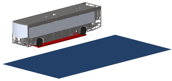
-
On the guide bar, make your selections.
The Ground and Survival Space are optional selections and can be activated from the hamburger menu.
- Bus: Selection of Bus components including survival space component if this one exists. This selection defines the components that will be moved by the tool to the impact position.
- Platform: Selection of tilting platform component that will be moved by the tool to the unstable position.
- Ground: If the option Create ground is deactivated in the hamburger menu, the ground selector is activated to allow the selection of either a rigid wall or a component. The ground defines the limit plane for the final impact position of the bus.
- Survival Space: If it exists in the model and the option Add survival space is activated in the hamburger menu, it allows the selection of a component defining it. The survival space does not contribute to mass, COG and inertia calculation of the selected bus components.
- Click
 to undo operations done in the guide bar.
 - Click
 and
and  to move to the previous/next guide bar.
Hamburger menu options:- Unit system:
- N, m, s, kg
- kN, mm, ms, kg
- N, mm, s, T
- Add survival space: Activating this option activates the selector in the guide bar.
- Create ground: Activating this option, the values below become editable, and the ground is created automatically. When this option is active the Ground entity selector does not appear in the guide bar.
- Offset and Friction: If the above is activated:
- Offset: Vertical distance between ground and platform.
- Friction: Defines the friction value in the RigidWall keyword.
- Moveback: Distance between ground and final impact position of the bus.
-
On the next guide bar, make your selections.
The next guide bar is dedicated to the calculation and rotation of the bus and platform to the unstable position.
Figure 3. 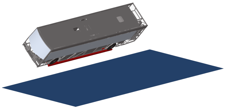
- Unstable Position: Rotates the bus to the unstable position based on the inputs defined in the microdialog (Platform Pivot, Rotation axis, Initial COG and Unstable COG).
- : Reset button in "Unstable
Position". Deletes position and transformations created at this stage and at
impact position stage, and moves the bus back to the starting
position.
-
move to the previous/next
guide bar.
- Platform Pivot: Pivot point on which the platform is rotated.
- Rotational axis: The axis of rotation.
- Initial COG: The center of mass in the initial position of the bus on the platform. It can be selected by you or calculated automatically using the calculate icon.
- Unstable COG: The center of mass in the most extreme angle of the platform. It can be selected by you or calculated automatically using the calculate icon.
-
On the next guide bar, make your selections.
The next guide bar is dedicated to the calculation and rotation of the bus to the impact position.
Figure 4. 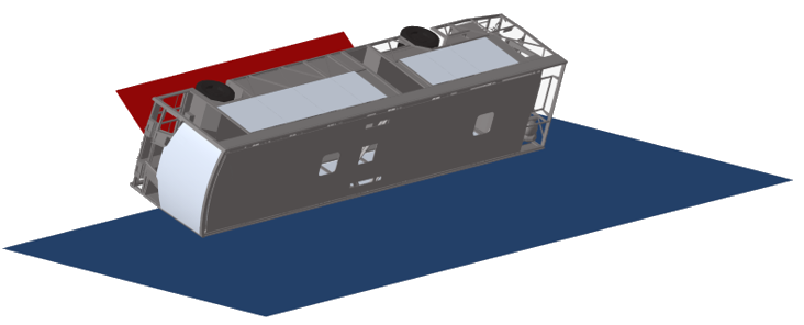
- Impact Position: Rotates the bus to the impact position based on the inputs defined in the microdialog (Impact Pivot, Rotation axis).
- : The reset button in the "Impact
Position" guide bar deletes the position and
transformations created at this stage and at the loadcase stage, and moves
the bus and platform back to the unstable position.
-
move to the previous/next
guide bar.
- Impact Pivot: Pivot point on which the bus is rotated to the final position.
- Rotational axis: The axis of rotation.
-
On the next guide bar, make your selections.
The next guide bar is dedicated to the creation of the loadcase.
- Create LoadCase: Creates entities and the loadcase include file.
- : The reset button in “Loadcase”
deletes all entities created in the include file for the load case
definition.
-
move to the previous/next
guide bar.
- Bus mass and Ixx: These values can either be defined by you or automatically calculated using the calculate icon.
- Omega: The calculated angular initial velocity after clicking Create LoadCase.
The tool creates an include file BusRollover_ECE-R66.inc that contains the loadcase definitions:- Positions and transformations of the bus and platform.
- Parameters for calculated values in the process and final angular velocity.
- The initial rotational velocity.
- The gravity.
- The rigid wall, if the ground is auto-created.