Nodes
Nodes are the most basic finite element entity. A node represents a physical position on the structure being modeled.
A node is used by an element entity to define the location and shape of that element. It is also used as temporary input to create geometry entities.
A node may contain a pointer to other geometric entities and can be associated directly to them.
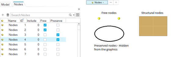
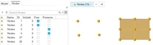
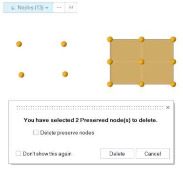
Nodes are considered to be used if they are referenced in the definition of an element, system, vector, group, load, equation, or are referenced by any card image on any entity. A "free" node is one that is not used by any element or used to define a vector or coordinate system as an example. Unused nodes and any loads that are attached to unused nodes are automatically deleted. Hence, the Temporary or Free node mark is provided as a holding area to save the nodes you are not currently using. Those nodes are saved as long as they are in the temporary/free node mark.
Nodes cannot be organized into components. Nodes can be organized into include files, which defines the solver include file they will be exported to.
A node is displayed a small circle or sphere, depending on the mesh graphics mode. Its color is always yellow.