Acoustic Cavity Meshing for Interior Noise
Acoustic cavity meshing for interior noise generates a fluid volume mesh used to calculate the acoustic modes (or standing waves) inside the air spaces of a vehicle or similarly enclosed structural model.
Acoustic cavity meshing can be a CPU-intensive process, especially with fine and/or complex meshes, however this can be offset by additional CPU cores. The Acoustic Cavity Mesher is multi-threaded to take advantage of multi-core environments.
Create an Acoustic Cavity Mesh for Interior Noise
Use the Interior tool to generate the mesh of tetrahedra or hexa-tetrahedra elements for prediction on noise.
Creating an acoustic cavity mesh is two-staged. First, create a voxel-based preview mesh. Second, select individual volumes, set element quality requirements, and create a smoother, more refined computational mesh for the selected volumes based off the parameters for element size, mesh type and element quality.
-
From the 3D ribbon, click the
Interior tool.
Figure 2. 
Restriction: The Interior tool is only available in the OptiStruct and Nastran solver interfaces. -
Click the Create tool to create acoustic cavity
mesh.
Figure 3. 
-
On the guide bar, click
 to define options for acoustic cavity meshing parameters.
- Target Element Size
- Enter the target element size for acoustic elements to be created. The actual mesh may vary from this depending on quality requirements.
- Min Element Size
- Enter the minimum element size for acoustic elements to be created. The elements created should not have a size less than the specified value.
- Max Element Size
- Enter the maximum element size for acoustic elements to be created. The elements created should not have a size more than the specified value. Max frequency is calculated based on this maximum element size and number of elements per wavelength.
- Max Frequency
- The max frequency value will be automatically calculated and populated based on max element size and No. of Elements Per Wavelength. It is also possible to specify the max frequency value, and then max element size will be calculated accordingly.
- Gap Patch Size
- Enter how large of a gap in the geometry the mesher will ignore. Gaps in geometry equal to or less than this size (in model units) will be patched or plastered over while the mesh is generated. Gaps larger than this will be taken into account and flooded with mesh to fill the cavities on the other side.
- Hole Patch Size
- Enter how large of a hole in the geometry the mesher will ignore. This value should be greater than your mesh size.
- Feature Angle
- Define feature angle.
- Seat Coupling
- Select a method for seat coupling.
- Choose Node to node remesh to obtain new node-connected cavities for the seats, matching seat nodes, and cavity nodes on a 1:1 basis.
- Choose MPC no remesh to connect the input seat components to the found cavities using MPCs, which allows node mapping at a ratio other than 1:1. Only use this option if the seat components are composed of solid elements. For proper MPC creation, the seat mesh size must be relatively similar to the size used to create the acoustic cavity mesh; in general, the size difference should be no more than 30 percent.
- Create Hole Elements
- Create permanent elements from the temporary elements used to patch over the holes, and store them in their own collector called ^patched_holes.
- Mesh Type
- Select the mesh type: hexa-tetrahedra or All tetrahedra for cavity mesh creation.
- Minimum Hexa Corner Jacobian
- Enter element quality criteria of Jacobian for solid elements.
- Minimum Tet-Collapse
- Enter element quality criteria of tet-collapse for solid elements.
- Display Structural Cavities
- Option to show as preview cavities or the chosen number for the largest ones.
- No. Elements Per Wavelength
- Enter the number to be used for max frequency calculation based on max element side.
- Air Density
- Density for the cavity mesh.
- WAVE Speed
- Speed of sound in the cavity mesh.
- Create Material and Property Cards
- Create acoustic cavity mesh with proper assignment of property and materials.
- Select structural components that surround the desired cavity. Select all of the components that enclose the air spaces. You can create meshes for multiple air spaces simultaneously, depending on which components you initially select.
- Select seat components to select the solid bodies representing the seat's acoustic cavity meshing, takes seating into account, and generates a separate volume mesh for each seat (bench seats are correctly treated as a single assembly, not broken up into individual seats based on the number of humans who could sit on them). This distinguishes the seats from the mesh that represents the air space.
-
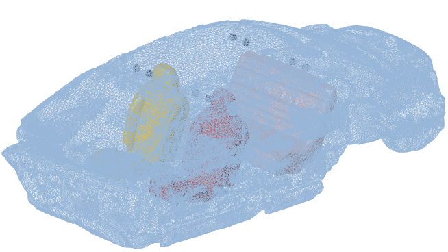
Click Preview to see the preview of the mesh.
Voxel-based preview of the mesh appears in the modeling window along with the list box. The entries in the list box allows you to show/hide/isolate the preview mesh. Select the preview mesh for which final acoustic cavity mesh needs to be created.
Figure 4. Simple Preview Mesh 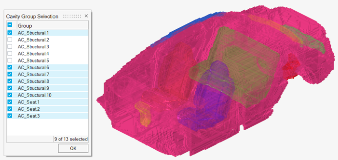
- Optional:
Select the response points from the .csv file.
Response points are defined in terms of nodal coordinates and tag label.
Figure 5. 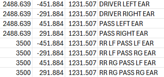
Figure 6. Simple Preview Mesh with Response Points Information 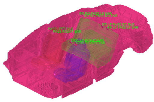
-
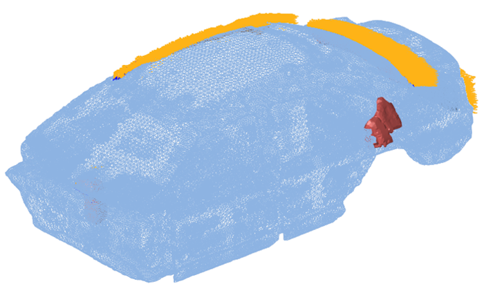
Create final acoustic mesh.
Figure 7. Final Acoustic Cavity Mesh 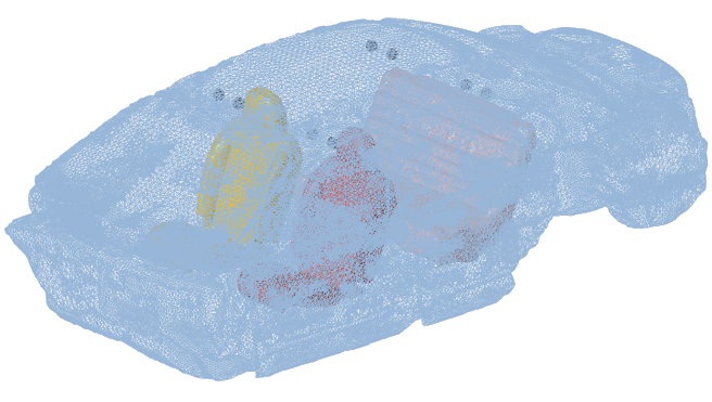
Review Fluid-Structure Interface
-
Click the F-S Interface tool to review interface
coupling between structure and cavity.
Figure 8. 
- Optional:
On the guide bar, click to define options for fluid-structure interface coupling.
- NORMAL
- Enter the fluid normal tolerance value to be specified in the ACMODL card.
- INTOL
- Enter the tolerance of inward normal value to be specified in the ACMODL card.
- SKNEPS
- Enter the fluid skin growth tolerance value to be specified in the ACMODL card.
- Create ACMODL card
- Select this option to write the ACMODL card in the exported solver.
- View Type
- Select a method to review fluid-structure interface.
- Choose Color elements on fluid faces to review the interface on fluid faces of acoustic mesh.
- Choose Highlight uncoupled fluid grids to show uncoupled fluid grids on the acoustic cavity mesh.
- Choose Highlight structure grids to show uncoupled structure grids on the structure mesh.
- Select structural components that surround the desired cavity.
- Select acoustic components to select the solid cavity mesh.
-
Show the interface.
This shows the coupling between structure and cavity indicating transfer of energy from structure to cavity. The pink color indicates properly coupled regions and blue color indicates uncoupled regions.
Figure 9. Fluid-Structure Interface 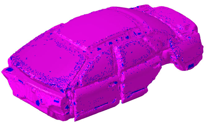
Review Fluid-Fluid Interface
-
Click the F-F Interface tool to review coupling between
different cavities created with MPC equations.
Figure 10. 
-
On the guide bar, click to define options for fluid-fluid interface coupling.
- All face grids
- Face grids through patch hole
- Face grids NOT through patch hole
- Tolerance
- Tolerance value to create MPCs between selected main and secondary components.
- Select main components that need to be coupled.
- Select secondary components that need to be coupled.
-
Show the interface.
This shows the coupling between main and secondary components with MPC equations.
Figure 11. Fluid-Fluid Interface with MPC Equations