In this tutorial, you will learn how to model point-to-curve (PTCV) and a
curve-to-curve (CVCV) joint.
A PTCV (point-to-curve) joint is a higher pair constraint. This constraint restricts
a specified point on a body to move along a specified curve on another body. The
curve may be open or closed, planar or in three-dimensional space. The point may
belong to a rigid, flexible or point body. This constraint can help avoid modeling
contact in some systems. It may prove advantageous since proper contact modeling
(refer to 3D Mesh to Mesh Contact Simulation) in many cases involves fine-tuning of
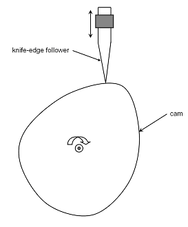
contact parameters. One good example of such a system is a knife-edge cam follower
mechanism. Modeling the contact between the cam and follower can be avoided by
defining a PTCV joint, with the curve being the cam profile and the point being the
tip of the follower.Figure 1. A Knife-Edge Cam Follower Mechanism
A CVCV (curve-to-curve) joint is another higher pair constraint. The constraint
consists of a planar curve on one body rolling and sliding on a planar curve on a
second body. The curves are required to be co-planar. This constraint can act as a
substitute for contact modeling in many cases where the contact occurs in a plane.
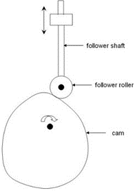
One such case is the cam-follower system, in which the follower is in the form of a
roller. Instead of modeling the contact between the cam and the follower, a CVCV
constraint between their profiles can be specified.Figure 2. Roller Type Cam-Follower Mechanism
In this tutorial, you will model a roller type cam-follower mechanism first using a
PTCV and later a CVCV constraint.
Before you begin, copy the file(s) used in this tutorial to your
working directory.
In this step, you will review the cam-follower roller model.
Start a new MotionView session.
From the Geometry ribbon, select the
Open tool.
Figure 3.
Browse to your working directory, select
CamFollower_start.mdl, and click
Open.
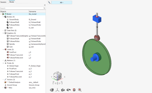
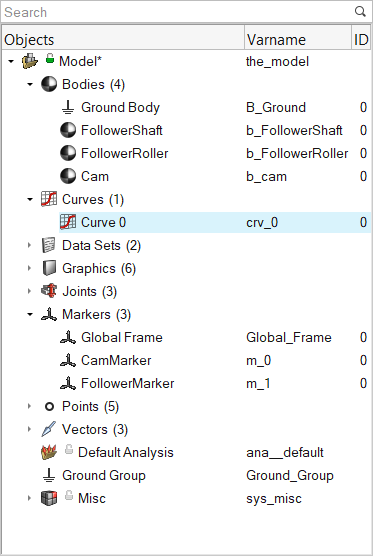
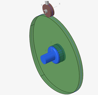
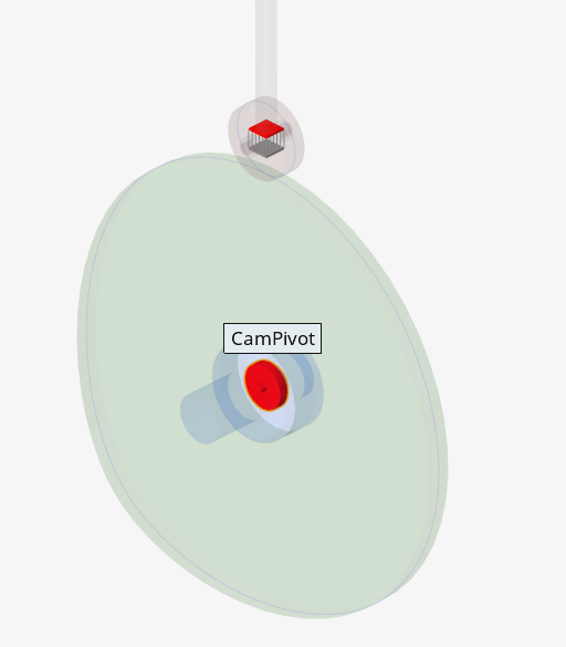
The model opens in the modeling window.Figure 4. Model Overview
Review the model. It consists of:
A Cam, a FollowerRoller,
and a FollowerShaft body
A CamPivot joint of type Revolute with Ground
Body
A FollowerTransJoint, which is a Translation
joint connecting FollowerShaft with Ground Body
A FollowerRoller joint, which fixes the
FollowerRoller to the FollowerShaft
A point FollowerPoint at the location where the
roller sits on the cam
Graphics Cam of type CADGraphics
Other graphics and points
Create Markers
In this step, you will create markers for the cam-follower model.
Select the Markers tool in one of the following
ways.
From the Model Browser, right-click on
Model and select Add > Reference Entity > Marker from the context menu.
From the Geometry ribbon, select the
Markers tool.Figure 5.
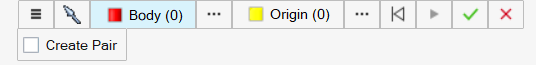
Create the CamMarker.
From the guide bar, verify that the
Body option is selected.
Figure 6.
From the modeling window, select the
Cam body.
From the guide bar, verify that the
Origin option is now selected.
Figure 7.
Pick the Global Origin by clicking anywhere in the modeling window.
From the microdialog, click
Create to create the Marker.
From the General section of the marker's Entity Editor, enter
CamMarker for
Label.
From the Orientation section, accept the default
values for the axes.
From the microdialog, click to finish
editing the current marker.
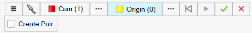
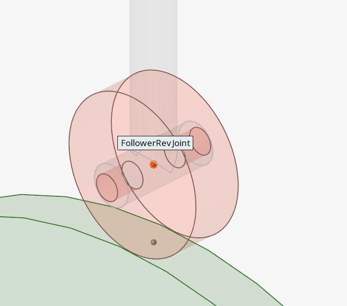
Create the FollowerMarker.
From the modeling window, select the
FollowerRoller body.
Select the FollowerRevJoint point as the
Origin.
Figure 8.
From the microdialog, click
Create to create the Marker.
From the General section of the Entity Editor, enter
FollowerMarker for
Label.
From the Orientation section, accept the default values for the
axes.
From the guide bar, click
Cancel to exit the
Marker context.
Create Curves
In this step, you will learn how to extract a curve from the Cam graphics and define
the follower roller’s curve using a math expression.
Create a Cam curve.
From the Geometry ribbon, select the
Line (Surface/Edge) tool from Lines tool
group.
Figure 9.
From the guide bar, verify that the
Faces option is selected.
From the modeling window, click on the Cam
body’s surface to select its outer edge.
From the guide bar, click the
Play button to create the curve.
The curve is now highlighted in blue, as shown in Figure 10.Figure 10. Cam curve created on the cam's periphery
Note: For the create Curve graphic, two entities are appended to
the Model Browser: a
graphic entity CurveGraphic used for
visualization and a corresponding Curve
entity that contains the curve’s point
coordinates.
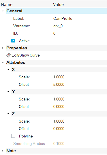
From the Model Browser, select the entity
Curve 0 under Model > Curves.
Figure 11.
From the General section of the Entity Editor, enter CamProfile
for Label and press Enter to confirm entry.
From the Attributes section, enter
5 for X Offset and hit
Enter to move the curve to the middle of the
Cam’s outer surface.
Clear the Polyline check box, which affects the
interpolation in between the curve’s points.
The CamProfile curve is now set.Figure 12.
Create the roller curve.
Note: The roller curve will be created as a circle using the sin and cos
functions in the Y-Z plane.
From the Model Browser, select the
Model parent system.
From the Model ribbon, select the
Spline2D tool from the Splines tool
group.
Figure 13.
From the guide bar, click the Create
and Edit button and then click
Cancel.
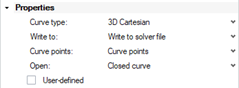
Configure the roller curve.
From the General section of the curve's Entity Editor, enter
FollowerRollerProfile for
Label.
From the Properties section, click the first
drop-down menu and change the Curve type to 3D
Cartesian.
Click the fourth drop-down and set Open to Closed
curve.
Figure 14. Set Follower Roller's profile curve properties
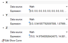
Expand the X section of the Properties section,
set Data source to Math to define the curve’s X
coordinates by a math expression.
Set Expression to
0.0*(0:1:0.01) and hit
Enter.
Note: The default curly braces in the expression can be removed.
Expand the Y section of the Properties section,
set Data source to Math.
Set Expression to 15*sin(2*PI*(0:1:0.01)) and hit
Enter.
Expand the Z section of the Properties section,
set Data source to Math.
Set Expression to 15*cos(2*PI*(0:1:0.01)) and hit
Enter.
Tip: Click the Edit/Show Curve button
to inspect the curve’s coordinates.
Figure 15. Define Follower Roller curve by math expressions
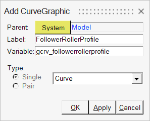
From Geometry ribbon, select the
Graphics tool to open the Add
CADGraphic dialog.
Figure 16.
From the Type section of the Add CADGraphic dialog, select
Curve from the drop-down menu.
Note: The title of the Add CADGraphic dialog will change to
Add CurveGraphic upon selecting
Curve.
Enter FollowerRollerProfile for Label.
Figure 17.
Click OK to create
the FollowerRoller’s curve graphic and exit the dialog.
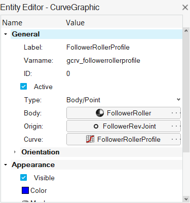
From the General section of the FollowerRollerProfile curve graphic's Entity Editor, verify type is set to
Body/Point.
Click the Ground Body field and select the
FollowerRoller by clicking on it in the modeling window or using the Advanced Selector.
Click the Global Origin field and select the
FollowerRevJoint point from the modeling window or using the Advanced Selector.
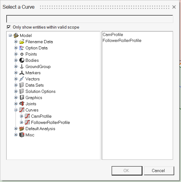
Select the Unresolved field and click to open the
Select a curve dialog.
From the Select a curve dialog, select the
FollowerRollerProfile curve under Model > Curves.
Figure 18.
Figure 19. Cam and FollowerRoller graphic's curves The newly created curves now appear in the modeling window.
From the menu bar, click File > Save As > Model and save the file as
CamFollower_PTCV.mdl.
Create the PTCV Joint
In this step, you will create the point-to-curve (PTCV) joint.
Enter the Advanced Joints context through one of the
following:
From the Model Browser, right-click on
Model and select Add > Constraint > Advanced Joint.
OR
From the Model ribbon, select the
Advanced Joints tool.Figure 20.
Create the PointToCurve advanced joint.
From the guide bar, verify that
PointToCurve is selected from the drop-down
menu.
Verify that Body 1 is highlighted and, from the modeling window, select the
FollowerRoller body.
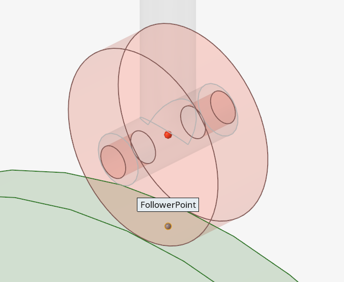
From the guide bar, verify that Origin is now
highlighted.
From the modeling window, select
FollowerPoint.
Figure 21.
From the guide bar, verify that Curve is now
highlighted.
Click the Advanced Selector next to
Curve to open the Select a Curve dialog (or simply
click on the graphic in the modeling window).
Select the CamProfile curve under Model > Curves and click OK.
Figure 22.
From the microdialog, click
Create to set up the Advanced Joint.
The Entity Editor of the Advanced Joint
is displayed.
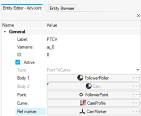
From the Entity Editor, edit the Properties of the PTCV
advanced joint.
From the General section, enter PTCV for
Label.
Select the Ref Marker collector and click twice
on the Advanced Selector to open the
Select a Marker dialog.
From the Select a Marker dialog, select
CamMarker under Model > Markers and click OK.
From the guide bar, click
Cancel to exit
the Advanced Joints context.
Note: Choosing the correct reference markers will cause the automatic selection
of the corresponding bodies, as shown in Figure 23.
In this step, you will specify a motion for the cam using an expression.
Enter the Motion context through one of the
following:
From the Model Browser, right-click on
Model and select Add > Constraint > Motion.
OR
From the Model ribbon, select the
Motions tool.Figure 24.
From the guide bar, verify that the
Joint option is selected.
From the modeling window, select the
CamPivot joint.
Figure 25.
From the microdialog, click
Create.
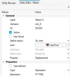
From the General section of the Entity
Editor, enter CamMotion for
Label.
Verify that Property is set to
Displacement.
From the Properties section, set Type to Expression and
enter `PI*TIME` in the Expression
field.
From the guide bar, click Cancel.
Figure 26. Cam motion Entity
Editor parameters
Specify Gravity
In this step, you will specify gravity for the model in the negative Z
direction.
From the Geometry ribbon, select the
Gravity tool from the Setup group.
Figure 27.
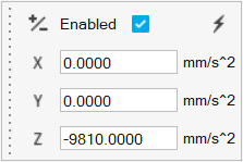
From the microdialog, verify that the
Enabled check box is selected.
Verify X is set to 0.
Verify Y is set to 0.
Verify Z is set to -9810.
Figure 28.
Specify Output Requests
In this step, you will specify output requests.
Enter the Output context through one of the
following:
From the Model Browser, right-click on
Model and select Add > General MDL Entity > Output.
OR
From the Analyze ribbon, select
the Requests tool from the Outputs tool
group.Figure 29.
From the guide bar, click the
Displacement drop-down menu and select
Expressions.
Click the Create and Edit icon .
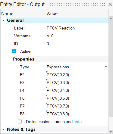
From the General section of the Entity
Editor, enter PTCV Reaction for
Label.
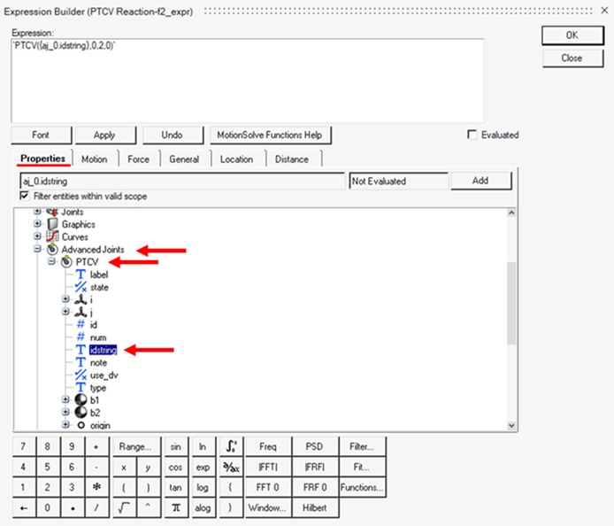
From the Properties section, select the field next to F2
and click to open the
Expression Builder dialog.
From the Expression Builder, enter
`PTCV({aj_0.idstring},0,2,0)`.
Figure 30.
Click OK.
Repeat steps 5 - 7 for F3, F4, F6, F7, and F8 by changing the third parameter in the expression
to 3, 4, 6,
7, and 8 accordingly.
Figure 31.
Note: The PTCV (id, jflag,
comp, ref_marker) function returns
the reaction on the PTCV joint:
id
ID of the PTCV joint
jflag
0 returns reaction on the I-marker and 1 on the J-marker of the
joint.
comp
Component of the reaction
1
Force magnitude
2
Force in X
3
Force in Y
4
Force in Z
5
Torque magnitude
6
Torque in X
7
Torque in Y
8
Torque in Z
ref_marker
Reference marker (0 implies Global Frame).
Right-click in the empty space of the modeling window
and select to exit the
Output tool.
Save the model .
Run the Model
The PTCV Cam follower model is ready to solve.
From the Model Browser, select
Default Analysis.
From the Analysis Parameter section of the Entity Editor, enter 4 seconds for
End Time.
From the Analyze ribbon, select the
Check Model tool to check the model for errors.
Figure 32.
From the Analyze Ribbon, select the Analysis settings
tool from the Run tool group to open the Run Motion
Analysis dialog.
Figure 33.
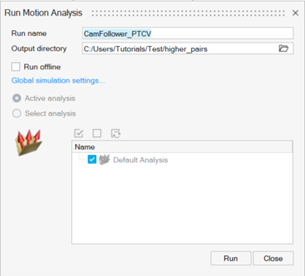
From the Run Motion Analysis dialog, configure the Motion
Analysis settings.
Enter CamFollower_PTCV for Run
name.
Set Output directory to your <working
directory>.
Figure 34. Run Motion Analysis window
Click Run
to initiate a live simulation, the progress of which can be viewed from
the Run Status dialog.
View Results
In this step, you will learn how to view the animation and plot the vertical
displacement of the follower roller.
Once the solver has finished and the Review Run Results
context is active , navigate to the Animation toolbar and click
Play to start the
animation.
From the Run Status dialog, click
Plot to open HyperGraph in a new page.
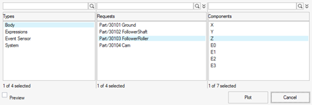
The Create Curves by File dialog opens with the
result CamFollower_PTCV.abf file pre-selected.
Plot the vertical displacement of the follower roller.
Under Types, select
Body.
Under Request, select Part/30103
FollowerRoller.
Under Component, select
Z.
Click Plot to plot the Z profile of the center
of mass of the follower roller.
Figure 35. Create Curves by File
Once the plot is created, click Cancel.
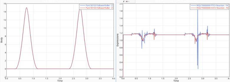
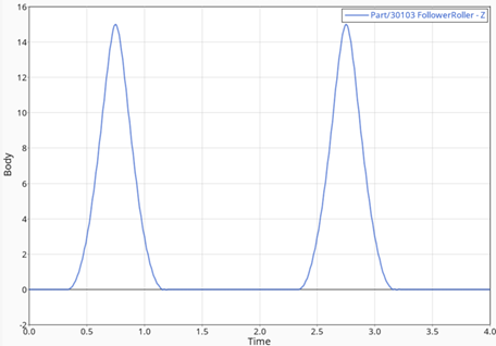
The profile for the Z displacement of the follower is displayed as in
Figure 36.Figure 36. Follower body Z-displacement plot
Check the Model for Potential Lift-Off
In this step, you will check the cam-follower mechanism for potential lift-off by
plotting the Z profile of the PTCV reaction on the follower roller.
In some cases, the dynamics of the system may cause the follower to lose contact with
the cam. This is called "lift-off." In such cases, modeling the system with a PTCV
will give you incorrect results because the joint constrains the follower point to
always be on the curve (and hence cannot model lift-offs). For such cases, you must
use contact modeling. However, you will want to start with a PTCV model since it is
a lot easier than modeling contact. Given this scenario, model the system using a
PTCV joint and monitor the PTCV joint reaction. If the reaction on the follower is a
‘pulling’ reaction, this indicates lift-off would have occurred and you must switch
to a contact model. Otherwise, the contact model is unnecessary. Now, you will check
the model you used in the tutorial. The follower is moving along the Z-axis, so any
negative reaction along the Z-axis is a 'pulling' reaction.
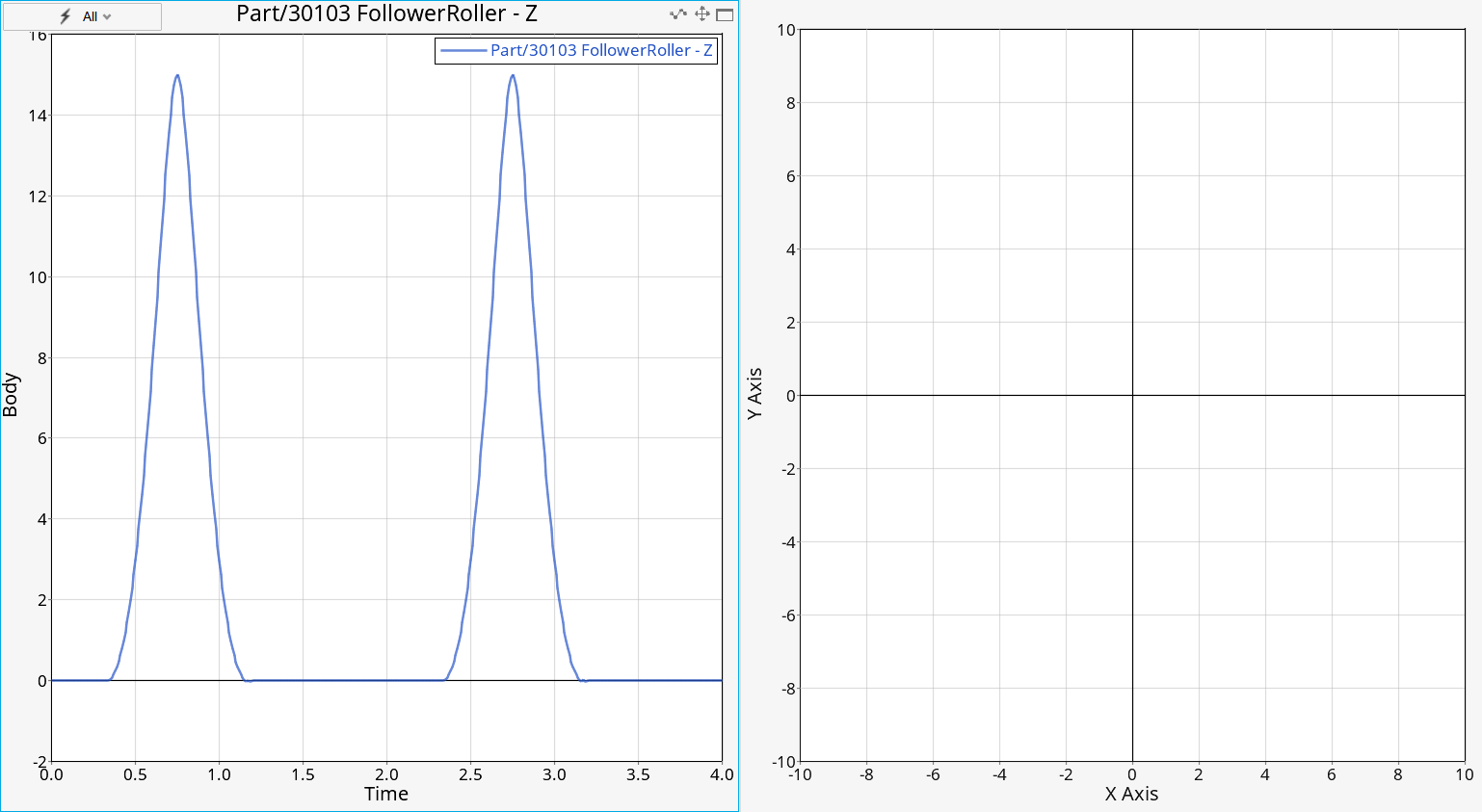
From the Page Controls toolbar, click and then
to
enable a vertical 2 window layout.
Figure 37.
Two windows are shown side by side.
Click on the right window to set it as active.
From the Line Chart ribbon, click the Open icon to open the Create Curves by
File dialog.
Configure the Create Curves by File dialog settings.
Under Types, select
Expressions.
Under Request, select REQ/7000000
PTCV Reaction.
Under Component, select
F4.
Click Plot and then Cancel.
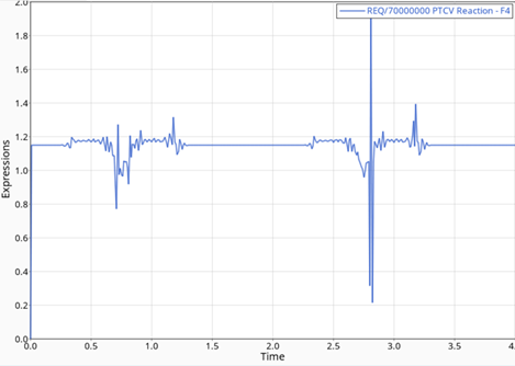
The Z profile of the PTCV reaction on the follower roller is as shown in
Figure 38.Figure 38. Z profile of the PTCV reaction on the follower roller
The Z component of the PTCV reaction on the Follower Roller is almost
always positive. Therefore, only a very slight tendency for lift-off is
evident in the simulation, so the PTCV model is deemed partly acceptable for
analyzing this mechanism.
Modify Joint to Enable Follower-Roller Rotation
In this step, you will prepare the model for simulating the cam follower with the
CVCV (curve-to-curve) joint.
Return to the MotionView model page.
From the Model Browser, select the
FollowerRollerJoint under Model > Joints to display its properties in the Entity Editor.
From the General section of the Entity
Editor, set Type to
Revolute.
From the Orientation section, verify
Method is set to Vector.
Click the Global Z field and then to
open the Select a Vector dialog.
From the Select a Vector dialog, select the
Global X vector under Model > Vectorsand then click OK.
Create CVCV Joint
In this step, you will create the CVCV (curve-to-curve) joint.
Enter the Advanced Jointsguide bar by doing one of the
following:
From the Model Browser, right-click on
Model and select Add > Constraint > Advanced Joint.
OR
From the Model ribbon, select the
Advanced Joints tool.Figure 39.
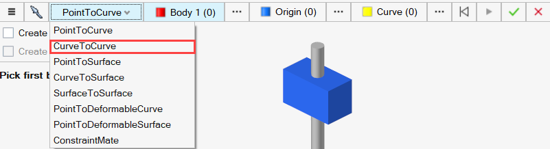
From the guide bar, click the
PointToCurve drop-down menu and select the
CurveToCurve option.
Figure 40.
From the modeling window, select
FollowerRollerProfile for Curve 1.
Select CamProfile for Curve 2.
From the microdialog, click
Create to set up the Advanced Joint and open the Entity Editor.
From the General section of the Entity
Editor, enter CVCVfor
Label.
Click the Global Frame field next to Ref marker 1 and
then to
open the Select a Marker dialog.
From the Select a Marker dialog, select
FollowerMarker under Model > Markers and click OK.
Repeat steps 7 and 8 for Ref marker 2 and select CamMarker instead of
FollowerMarker.
From the guide bar, click
Cancel to exit the
Advanced Joints guide bar.
Create output for CVCV.
From the Model Browser, select PTCV
Reaction under Model > Outputs and press Ctrl + C to copy
it.
Select the Model system and press
Ctrl + V to paste it.
Output 1 is created under Model > Outputs.
From the Entity Editor,
rename Output 1 to CVCV Reaction.
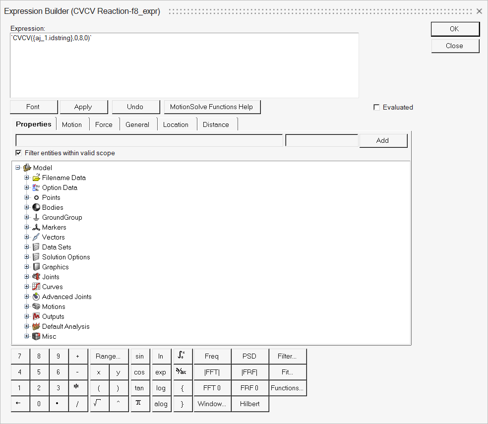
For expressions F2 to F8,
change the text PTCV to CVCV and aj_0 to
aj_1.
For instance, F8 expression should read
`CVCV({aj_1.idstring},0,8,0)`.Figure 41.
Deactivate the PTCV joint and output.
From the Model Browser, select the
PTCV advanced joint under Model > Advanced Joints.
From the General section of the Entity Editor,
clear the Active check box.
Repeat steps 12.a and 12.b for the PTCV Reaction under Model > Outputs.
Run the Model
In this step, you will run the cam-follower roller model.
From the Model ribbon, select the Check
Model tool and check the model for errors.
Figure 42.
From the Analyze ribbon, select
Save to save the model before running the
analysis.
Figure 43.
From the Analyze Ribbon, select the
Analysis settings tool from the Run tool group to
open the Run Motion Analysis dialog.
Figure 44.
From the Run Motion Analysis dialog, configure the Motion
Analysis settings.
Enter CamFollower_CVCV for Run name.
Set Output directory to your <working
directory>.
Click Run
to initiate a live simulation, the progress of which can be viewed from
the Run Status dialog.
View Results
Review and compare the results.
Once the solver has finished, navigate to the previously created plot window
for roller Z displacement in HyperGraph.
Click on the left window to set it as active.
From the Line Chart ribbon, select the Open file icon
and, from the Create Curves by
File dialog, click next to Choose
Data File.
Navigate to your working directory and select the
CamFollower_CVCV.abf file.
Plot the Z displacement of the FollowerRoller.
Under Types, select Body.
Under Requests, select Part/30103
FollowerRoller.
Under Components, select Z.
Click the right window to set it as active.
Overlay the reaction force of the CVCV joint with that of the PTCV joint in the
other window.
Under Types, select Expressions.
Under Request, select REQ/7000000 PTCV
Reaction.
Under Component, select F4.
Figure 45. Z profile of the PTCV reaction on the follower roller
From the menu bar, click File > Session > Save and save the file as
sess_cam_follower.mvw.


 to create the Marker.
 to finish
editing the current marker.
to finish
editing the current marker.
 to exit the
Marker context.
to exit the
Marker context.

 to create the curve.
The curve is now highlighted in blue, as shown in Figure 10.
to create the curve.
The curve is now highlighted in blue, as shown in Figure 10.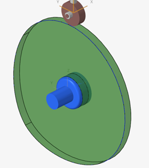

 .
.

 .
.


 to open the
Expression Builder dialog.
to open the
Expression Builder dialog.
 to exit the
Output tool.
to exit the
Output tool.
 .
.


 , navigate to the Animation toolbar and click
Play
, navigate to the Animation toolbar and click
Play
 to start the
animation.
to start the
animation.
 and then
 to
enable a vertical 2 window layout.
to
enable a vertical 2 window layout.
 to open the Create Curves by
File dialog.
to open the Create Curves by
File dialog.

 next to Choose
Data File.
next to Choose
Data File.