MV-1060: Build a Pendulum Model Using MDL Statements
In this tutorial, you will learn how to create a pendulum model
using Model Definition Language (MDL), run a dynamic simulation of the model, plot the
rotation of the pendulum and view the animation.
MDL stands for Model Definition Language. A MotionView
model is an object that holds the information in the form of this language which is
required to describe a mechanical system. The complete information about the model is
stored in the MDL format. MDL is an ASCII programmable language. Some benefits of MDL
include the following:
You can open and edit in any text editor.
It assists with model debugging.
You can use conditional statements "if" for custom modeling requirements.
You can build modular and reusable models.
You can parameterize the models.
You can use modeling entities which are not available through GUI (for example,
CommandSets).
Section 1: Entities in MDL
A modeling entity is saved to MDL in the form of MDL statements. All MDL
statements begin with an asterisk (*).
There are two types of entities:
General Entities
Definition Based Entities
General Entities
Have one statement to define the entity. They may have
one or more statements to set their properties.
Some examples include points, bodies, joints, etc.
Each general entity has certain properties consistent
with its type. For example, a point has the properties
x-coordinate, y-coordinate, z-coordinate, label, state,
and varname (variable name).
Definition Based Entities
Are defined through a block statement, called
definition, and its instance is created in a model by an
instantiation statement.
The block generally begins with a
*Define() statement and end with
a *EndDefine() statement.
The entity (or block) is comprised of a series of other
MDL entities or members.
These entities are reusable. Once defined, the same
entity-definition may be instantiated several times
within the same model or different model files.
Some of the commonly used user-defined entities are outlined in the table
below:
Entity
Description
System
A system entity defines a collection of modeling
entities. These definitions may be used repeatedly
within the same model or different MDL model files. A
model can be organized into different systems. Examples
of system entities include SLA suspension system, wiper
blade system, and power-train system. Systems can be
hierarchical in nature (for example, a system can be a
child of another system).
Assembly
An assembly is similar to a system entity, except
that the definition resides in a separate file than the
model file.
Analysis
An analysis is a collection of entities (bodies,
joints, etc.) describing a particular analysis task or
event applied to a model. For example, a static ride
analysis is one of the analysis that can be applied to a
model. An analysis can only be instantiated under Model
(the top level root system). A system can be a child of
an analysis, however the reverse is not true.
Dataset
A dataset is a collection of user-defined variables
of type integer, real, string, Boolean, or filename.
These variables can be referred or parameterized to
other entity properties. Datasets are displayed in a
tabular form, thereby offering a single window to modify
a model. Generally, design variables are collectively
defined in the form of a dataset. A dataset can be
instantiated within a system or an analysis.
Template
A template is a utility that uses the Templex program in the
application. It can be used to create user-defined
calculations and codes embedded into the model. The
output of such code can be written out to solver deck or
execute another program. Another use is to implement
solver statements and commands not supported by MDL and
to generate text reports.
Note: The system, assembly, and analysis are together referred to as
container entities (or simply containers).
Section 2: Properties of Entities
Each entity has variable, label, and other properties associated
with it.
Each entity should have a unique variable name.
Following is the recommended convention for variable names which
allows the user to identify the modeling entity during debugging.
You are not restricted to this nomenclature, however you are
encouraged to adopt it.
This list of entities and their properties is not comprehensive. For a
complete list, refer to the MDL Language Reference on-line help.
Table 1. General entities, their naming conventions, and
properties
Table 2. User-defined entities, their naming conventions, and
properties
Definition Based Entities
Naming Convention
Properties
System
sys_
Label, varname, state
Analysis
ana_
Label, varname, state
Dataset
ds_
Label, varname, state
Template
tmplt_
Label, varname, state
To access entity properties; use the entity varname, followed by a dot
separator, followed by the property. Below are some examples:
Entity Varname
Varname Represents
b_knuckle
A body representing the knuckle in the mechanical
system.
p_knuckle_cg
A point representing the center of mass point for the
knuckle body.
Entity Property Name
Property Accessed
b_knuckle.cm
The center of mass marker of the knuckle body,
b_knuckle.
b_knuckle.cm.id
The ID of the center of mass marker of the knuckle
body, b_knuckle.
p_knuckle_cg.x
The x coordinate of
p_knuckle_cg.
Section 3: Global Variables
MotionView comes with Global Variables, by
default, which are available for use anywhere in the model. These variables
are case sensitive.
The table below lists some commonly used keywords and
what they represent:
Table 3. Common keywords in MotionView
B_Ground
Ground body
P_Global_Origin
Global Origin
V_Global_X, V_Global_Y,
                                                  V_Global_Z
Vectors along the global XYZ axes
Global_Frame
Global reference marker
MODEL
Reference to the top level system of the
model.
Section 4: MDL Statement Classification
Topology Statements
These are statements that define an entity and establish
topological relation between one entity and the other. For
example, *Body(b_body, “Body”, p_cg). In this
example, the *Body statement defines a body
having its CG at point p_cg. Through this
statement the body (b_body) is topologically
connected to point p_cg.
Property or Set Statements
These statements assign properties to the entities created by
topological entities. For example, *SetBody()
is a property statement that assign mass and inertia properties
to a body defined using *Body(). Since most
of the property statements begin with “*Set”,
they are generally referred as Set statements.
Definition and Data
Building upon the concept of a definition block, these
terminologies are used specifically with regard to container
entities such as Systems, Assembly, and Analysis.
The block of
statements when contained within a
*Define() block are termed as a
Definition. The statements within the block may include:
Topology statements that define entities.
Set statements that assign properties. These Set
statements within a definition block are called
"Default Sets", as they are considered as default
values for the entities in the definition.
Any statements or block that resides outside the
context of *Define() block are termed as
Data. These include:
Set statements within a
*BeginContext() block that
relate to entities within a system, assembly, or
analysis definition.
Some of the *Begin statements, such as
*BeginAssemblySelection and
*BeginAnalysis.
Section 5: MDL Model File Overview
MDL model file is an ASCII file; it can be edited using any text
editor.
All statements in a model are contained within a *BeginMDL() -
*EndMDL() block.
The syntax of the MDL statement is an asterisk (*) followed by a
valid statement with its arguments defined.
Statements without a leading asterisk (*) are considered comments.
In this tutorial, comment statements are preceded by // to improve
readability. The comments are not read in by the MotionView
graphical user interface and are removed if the model MDL is saved
back or saved to a different file.
MDL accepts statements in any order, with a few exceptions.
To help you learn this language, the code in the tutorial examples will
follow this
structure:
//comments about the MDL file
*BeginMDL(argument list)
//Topology section
*Point…
*Body…
*System(…)
// definitions sub-section
*DefineSystem(..)…
..
.*EndDefine()
//Property of entities directly in *BeginMDL()//Property section for
entities within Systems and analysis
*BeginContext()
..
..
*EndContext()
.
*EndMDL
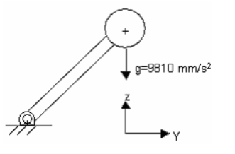
Figure 1 shows the
schematic diagram of a pendulum. The pendulum is connected to the ground through a
revolute joint at the global origin. The pendulum falls freely under gravity, which
acts in the negative global-Z direction. Geometry and inertia properties are shown
in the figure. The center of mass of the pendulum is located at (0, 10, 10). Figure 1. Schematic representation of the pendulum The model uses the following MDL statements:
In this step you will create an MDL model file for the pendulum model.
Open a text editor.
Create comment statements describing the purpose of the model:
//Pendulum falling under gravity
//date
Create a *BeginMdl() - *EndMdl() block to signify the
beginning and the end of the model file.
Important: All other MDL model file statements should be between
these block statements.
This is the syntax for the
*BegingMdl() statement:
*BeginMdl(model_name, "model_label")
model_name
is the variable name of the model.
model_label is the
descriptive model of the label.
For the purpose of this tutorial, you
will use:
*BeginMdl(pendulum, "Pendulum Model")
*EndMdl()
Tip: Look for the syntax of the corresponding statements by navigating
to the menu bar and clicking Help > Index. Then type the statement in the Index. In MDL statements,
only keywords are case-sensitive.
Create Entity Declarations
Here, you will create the entity declarations necessary for the problem.
Use the *Point() statement to create a point for the
pendulum pivot:
//Points
*Point(p_pendu_pivot, "Pivot Point")
The syntax of the *Point() statement is
*Point(point_name, "point_label", [point_num]).
point_name The variable name of the point
(p_pendu_pivot).
point_label The descriptive name of the point
(Pivot Point).
point_num An optional integer argument assigned to the
point as its identity number. You will not use one for this
tutorial.
Use the *Point() statement to create a point for the
pendulum center of mass:
*Point(p_pendu_cm, "Pendulum CM")
Use the *Body() statement to define the ball’s body:
//Bodies
*Body(b_link, "Ball", p_pendu_cm)
The syntax for the *Body() statement is
*Body(body_name, "body_label", [cm_origin], [im_origin],
[lprf_origin],[body_num]).
body_name The variable name of the body
(b_link)
body_label The descriptive label of the body that
appears in the graphical display (Ball).
cm_origin An optional argument for the origin point of
the inertia marker of the body (p_pendu_cm).
im_origin An optional argument for the origin point of
the inertia marker of the body (not used in this model).
lprf_origin An optional argument for the origin point
of the local part reference frame of the body (not used in this
model).
body_num An optional integer argument assigned to the
body as its entity number (not used in this model).
Square brackets [] in the description of any statement
syntax indicate an argument is optional.
Use the *Graphics() statement (one for cylinder and one for
sphere) to display the link and the sphere:
The syntax for the sphere graphic is *Graphic(gr_name, "gr_label",
SPHERE, body, origin, radius).
gr_name The variable name of the graphic
(gr_sphere).
gr_label The descriptive label of the graphic
(pendulum sphere graphic)
SPHERE This argument indicates that the graphic is a
sphere.
body The body associated with the graphic
(b_link).
origin The location of center point of the sphere
(p_pendu_cm).
radius The radius of the sphere
(1).
The syntax for the cylinder graphic is *Graphic(gr_name, "gr_label",
CYLINDER, body, point_1, POINT|VECTOR, orient_entity, radius,
[CAPBOTH|CAPBEGIN|CAPEND]).
gr_name The variable name of the graphic
(gr_link).
gr_label The descriptive label of the graphic
(pendulum link graphic).
CYLINDER This argument indicates the graphic is a
cylinder.
body The body associated with the graphic
(b_link).
Point 1 The location of one end of the cylinder
(p_pendu_pivot).
POINT|VECTOR Keyword to indicate the type of entity
used to orient the cylinder. If POINT is used, the
following argument should resolve to a point, otherwise it should
resolve to a vector.
orient_entity The variable name of the entity for
orienting the cylinder (p_pendu_cm).
radius The radius of the cylinder
(0.5).
[CAPBOTH|CAPBEGIN|CAPEND] An optional argument that
identifies if either or both cylinder ends should be capped
(closed).
Use the *RevJoint() statement to create a revolute joint at
the pivot point:
//Revolute Joint
*RevJoint(j_joint, "New Joint", B_Ground, b_link, p_pendu_pivot, VECTOR,
V_Global_X)
The
syntax for the *RevJoint() statement is
*RevJoint(joint_name, "joint_label", body_1,body_2, origin,
POINT|VECTOR, point|vector, [ALLOW_COMPLIANCE])
joint_name The variable name of the joint
(j_joint).
joint label The descriptive label of the revolute joint
(New Joint).
body 1 The first body constrained by the revolute joint
(B_ground).
body 2 The second body constrained by the revolute
joint (b_link).
origin The locations of revolute joint
(p_pendu_pivot).
POINT|VECTOR Keyword to suggest the method of
orientation for the joint using a point or vector
(VECTOR).
point|vector A point or vector that defines the
rotational axis of the revolute joint
(V_Global_X).
[ALLOW COMPLIANCE] An optional argument that indicates
the joint can be made compliant (a joint that is compliant is treated
like a bushing and can be toggled between compliant and
non-compliant).
Use the *Output - output on entities statement to create an
entity output statement:
The syntax for the output statement is *Output(out_name, "out_label",
DISP|VEL|ACCL|FORCE, entity_type, ent_name, [ref_marker],
[I_MARKER|J_MARKER|BOTH_MARKERS]).
out_name The variable name of the output
(o_pendu).
out_label The descriptive label of the output
(Disp Output).
DISP|VEL|ACCL|FORCE An argument that indicates whether
the output type is displacement, velocity, acceleration, or force
(DISP).
entity_type Keyword to indicate the type of entity on
which the output is being requested. Valid values are:
BODY|JOINT|BEAM|BUSHING|FORCE|SPRINGDAMPER (BODY).
ent_name The entity on which output is requested.
(b_link).
ref_marker An optional argument for the reference
marker in which the output is requested.
I_MARKER|J_MARKER|BOTH_MARKERS Keyword to indicate the
capture of output on the I marker, J Marker or both markers. The default
is both markers.
Use the *SetSystem(), *SetPoint(), and
*SetBody() statements to set property values for the
entities you created in the MDL file:

 (Open Model).
Tip: You can also click from the menu bar.
(Open Model).
Tip: You can also click from the menu bar. (YZ Rear Plane View)
button.
The model will look as shown in Figure 2:
(YZ Rear Plane View)
button.
The model will look as shown in Figure 2: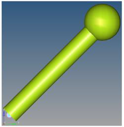
 (Run) panel
button.
(Run) panel
button.
 (file browser) and specify the name of the
.xml as pendulum.
(file browser) and specify the name of the
.xml as pendulum.
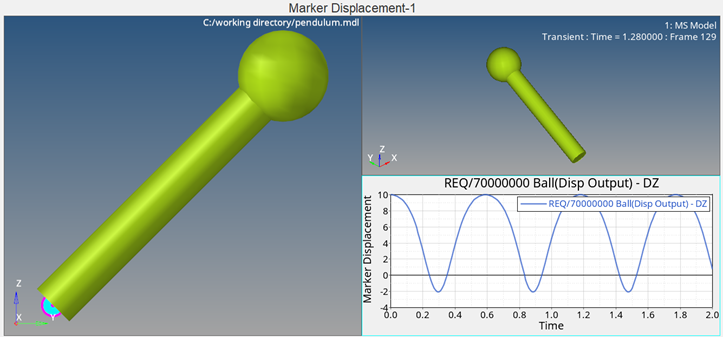
 (Start/Pause Animation) button to view the
animation.
Note: You can click the button again
(Start/Pause Animation) button to view the
animation.
Note: You can click the button again to pause the
animation.
to pause the
animation. (Fit Model/Fit All Frames) icon to fit the
visualization in all frames of the animation.
(Fit Model/Fit All Frames) icon to fit the
visualization in all frames of the animation.