
OS-T: 1520 Finite Sliding of Rack and Pinion Gear Model
This tutorial outlines the procedure to perform finite sliding analysis on a rack and pinion gear model. The circular gear is called the pinion and it engages teeth on the linear bar called the rack.
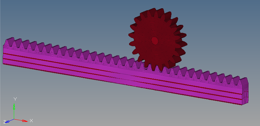
In small sliding analysis, not only is the relative sliding between main and secondary relatively small but the contact search is done only at the beginning of the simulation. While for finite sliding the contact search is updated for every increment of the analysis. In this case, as you can see, the circular gear must be in contact with the entire rack over the course of the simulation, so contact status needs to be updated for every increment to capture the entire motion and hence finite sliding is necessary.
This tutorial helps you define finite sliding contact between the circular gear and rack. The gear is held fixed at the center in all dof while the rack is given displacement in x dof but constrained in all other dof. All constraints and enforced displacements have already been defined in model. Set segments to define the secondary and main surfaces are also pre-defined in the model. Contact stabilization has been defined for the contact to help stabilize any rigid body motion before contact gets established. A very tiny end-of-subcase stabilization also has been specified to overcome any temporary instabilities that may sometimes occur at end-of-analysis.
Launch HyperMesh and Set the OptiStruct User Profile
-
Launch HyperMesh.
The User Profile dialog opens.
-
Select OptiStruct and click
OK.
This loads the user profile. It includes the appropriate template, macro menu, and import reader, paring down the functionality of HyperMesh to what is relevant for generating models for OptiStruct.
Open the Model
- Click .
- Select the finite_sliding.hm file you saved to your working directory.
-
Click Open.
The finite_sliding.hm database is loaded into the current HyperMesh session, replacing any existing data.
Set Up the Model
Review Material Properties
The imported model contains a large amount of pre-defined information which allows you to focus on the finite sliding section in this tutorial. All material and properties are pre-defined for the circular gear and rack. The material properties of steel are assigned to both components.
- In the Model Browser, Materials folder, right-click on steel and select Card Edit from the context menu.
-
Verify that the values on the MAT1 Bulk Data Entry for the
material properties of steel are input as shown in Figure 2.
Young's Modulus of Elasticity = 2.1 x 10⁵ N/m2
Poisson's Ratio = 0.3
Figure 2. Review the material - steel 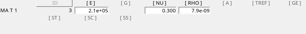
- Click return to complete the review.
Review Set Segment and Generate Finite Sliding Contact
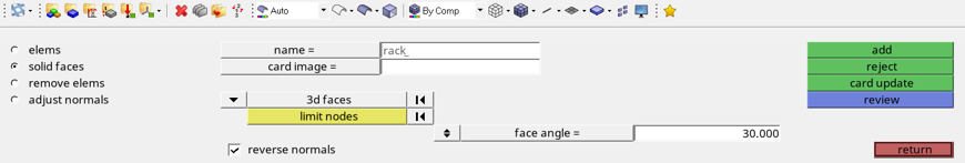
- In the panel area, go to the Analysis page and click set segments to review the already created set segment.
- Go to the solid faces subpanel.
-
Review the contact surface for rack.
- Click name.
- Select rack.
- Click review.
Figure 4. Review of set segment for rack 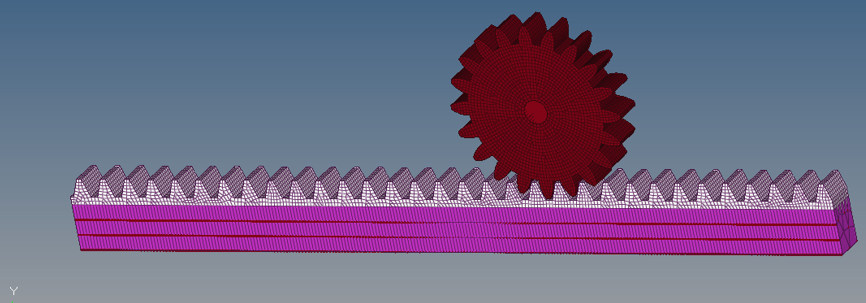
- Review the set segment for gear.
- Click return to exit the seg segment panel.
-
Create a set segment.
-
Change the entity type to sets for both main and
secondary.
Figure 5. Select main and secondary sets 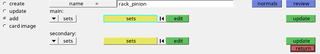
-
Change the entity type to sets for both main and
secondary.
-
To review the interface, click review.
Figure 6. Review interface 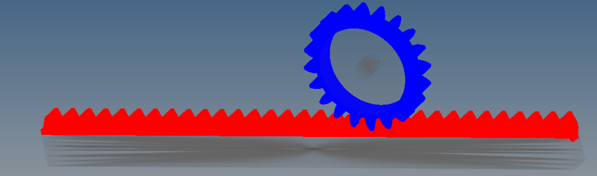
-
Edit the set segment.
- Go to the card image subpanel.
- Click edit to edit the contact interface.
- Set TYPE to SLIDE.
- Set DISCRET to S2S.
- Set TRACK to FINITE.
Surface-to-surface a finite sliding contact without friction have been defined.Figure 7. S2S, Finite Sliding Contact Definition 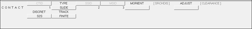
- Click return to exit the interfaces panel.
Review Parameters, Contact Output Request and Loadstep Definition
Large displacement formulation needs to be activated for finite sliding contact.
- Click on control cards panel to review the parameter and turn on LGDISP.
- Click next twice and select PARAM.
- Verify PARAM, LGDISP is set to1.
- Click return.
- Click GLOBAL_OUTPUT_REQUEST.
-
Verify CONTF is selected.
Note: CONTF gives contact output results, like contact pressure, gap penetration, sliding distance, and so on.
- Click return twice to exit the control card panel.
-
Click the loadsteps panel to review the pre-defined
loadstep.
The SPC load and NLPARM load step input have been defined and analysis should be of type nonlinear static. The SPC load points to the fixed constraints on the circular gear, as well as enforced displacement on the bottom of rack. The NLPARM load step input defines the nonlinear parameters.
Submit the Job
-
From the Analysis page, click the OptiStruct
panel.
Figure 8. Accessing the OptiStruct Panel 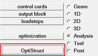
- Click save as.
-
In the Save As dialog, specify location to write the
OptiStruct model file and enter
rack_pinion for filename.
For OptiStruct input decks, .fem is the recommended extension.
-
Click Save.
The input file field displays the filename and location specified in the Save As dialog.
- Set the export options toggle to all.
- Set the run options toggle to analysis.
- Set the memory options toggle to memory default.
- Click OptiStruct to launch the OptiStruct job.
View the Results
-
Once you receive the message Process completed
successfully in the command window, click HyperView.
HyperView is launched and the results are loaded. A message window appears to inform you of the successful model and result files loading into HyperView.
- Click Close to exit the message window, if one appears.
-
On the toolbar, click
 (Contour).
- Under Result type, from the first drop-down menu, select Displacement (v).
-
Under the second drop-down menu, select X.
Figure 9. Plot Displacement (v) in HyperView 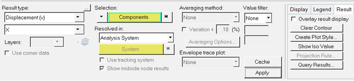
Figure 10. Contour plot panel in HyperView 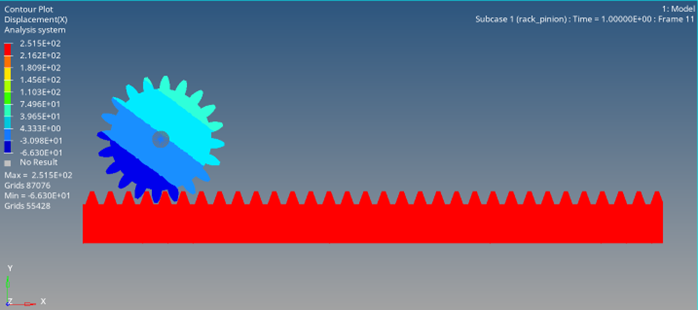
- Optional:
Animate the results using the Set Transient Animation Mode in HyperView.
Figure 11. 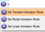
- Optional: Select other result types in the Contour panel and click Apply.