When using the soft soil road contact method, if the track
link geometry features different dimensions from the ones specified in the track properties,
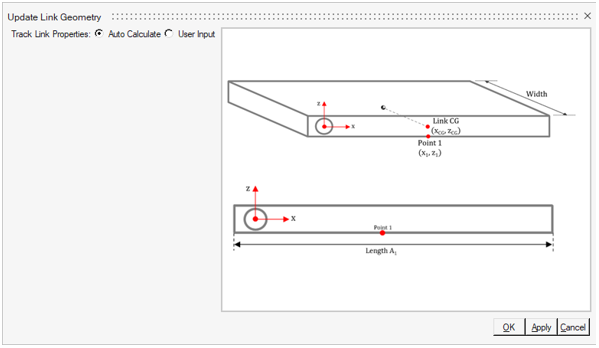
it is required to use the update link geometry option.Figure 1. Update Link Geometry dialog
The default option is set to Auto Calculate, this option
considers the parameters specified in the track properties section. In case of different
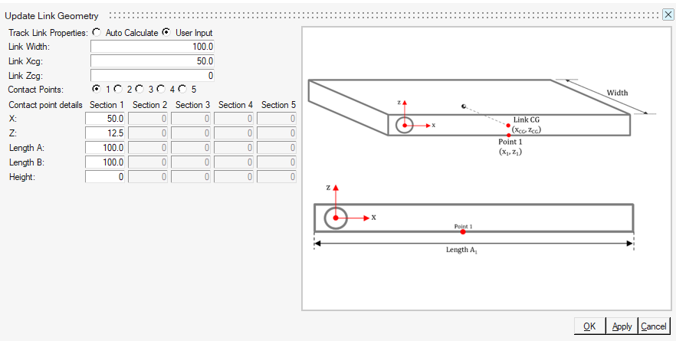
track link geometry, the User Input option allows modify the
dimension of the track link.Figure 2. User input option in Update Link Geometry dialog
The contact points define how many points will represent that track link. The
maximum points allowed in the model is five. The X and Z coordinate of the contact points
must be referenced by the track pin center (red coordinate system). The Xcg and Zcg are the
longitudinal and vertical referential distances of link CG location from pin center. The
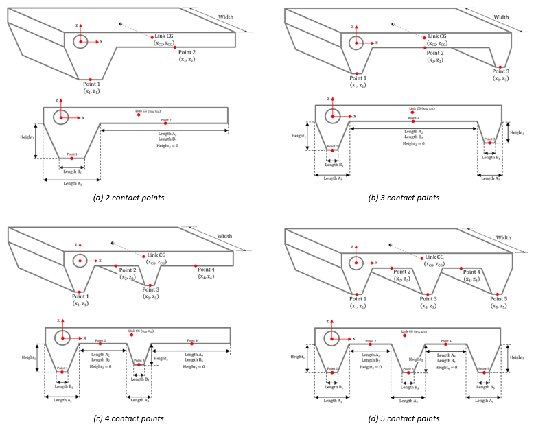
figure below illustrates the track links with 2, 3, 4, and 5 points.Figure 3. Contact points available in Update Link Geometry
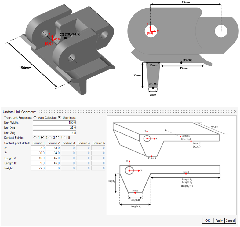
The figure below shows an example of a CAD track link using 2 contact points and the equivalent
parameters in the Update Link Geometry dialog.Figure 4. Example of 2-point contact track link
Note: The coordinate system X and Z (0,0) located in the track
pin center, shown in the picture above, indicates the contact points must be referred to
the track pin center in the Update Link Geometry dialog. This information should not be
misunderstood with the track link center location specified in the CAD file as indicated
in Create Tracks.