Apply Thickness to Midsurface
Use the Map Thickness tool to apply thickness values to shell elements on midsurfaced geometry.
The thickness will be assigned on the midmesh either on node card, element card, nodal thickness on element card or also as properties on elements depending on the solver interface you are using.
Restriction: Only available in the OptiStruct,
Radioss, Abaqus,
LS-DYNA, PAM-CRASH 2G, or
Nastran solver interfaces.
-
From the 2D ribbon, click the Map Thickness tool.
Figure 1. 
- Optional:
On the guide bar, click
 to define map
thickness options.
to define map
thickness options.
- Activate the Source selector on the guide bar, choose an entity type, then select source entities.
- Activate the Target selector on the guide bar, choose an entity type, then select target entities.
- On the guide bar, click Apply Thickness.
Options for Map Thickness
Access the following options by clicking ![]() on the
Elements ribbon: Map Thickness tool
guide bar.
on the
Elements ribbon: Map Thickness tool
guide bar.
Define Thickness Options
- Minimum thickness/Maximum thickness
- Define a thickness to assign calculated thicknesses.
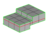
- Assign offset to elements/sections
- To assign an offset value to elements if they are not in the middle of
the selected geometry, select the Assign offset to
elements/sections checkbox.
Figure 3. Element Offset Off 
Figure 4. Element Offset On 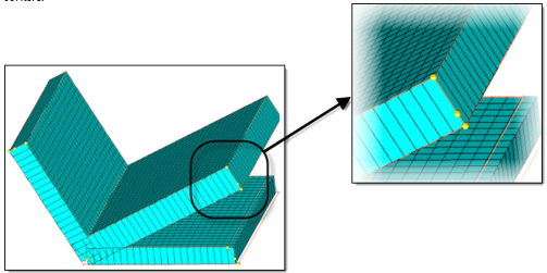
- Group elements by thickness interval
-
- Automatic Method
- Groups elements with similar thicknesses together, and assigns an average thickness to the groups based on the “Factor of thickness” interval range input.
- For example, suppose you enter a Factor of thickness value
of 0.2. Starting from the element with the smallest
thickness, elements with similar thickness are grouped
together, such that the difference between maximum and
minimum thickness in one group does not exceed 0.2 times the
maximum thickness in the group. The thickness values of
elements in a group is averaged and assigned to all of the
elements in the group (or to the property.)
Figure 5. 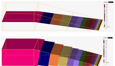
- If more thickness interval range control is required switch
“Thickness interval” to User defined and specify the
thickness interval range required.
Figure 6. 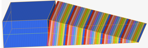
- Method Fixed Interval
- Control thickness properties at constant intervals.
- Assign thickness to groups has four methods: Average,
Mid-interval, Min-interval and Max interval.
- Average
- All thickness in the group are calculated and averaged
- Mid-interval
- Middle of the thickness interval range.
- Min-interval
- Minimum of the thickness interval range.
- Max-interval
- Maximum of the thickness interval range.
- For a user defined thickness interval range 0.05
and starting thickness 0.2 for a calculated
thickness of 0.42 will has assigned thickness
value 0.4 for mid-interval, 0.4 for min-interval
and 0.45 for max-interval.
Figure 7. 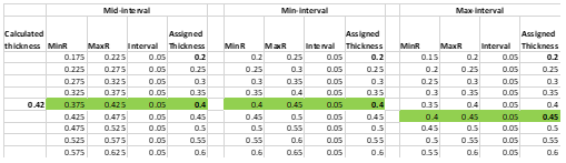
- Merge isolated elements with adjacent groups
- Merges isolated elements into adjacent groups. The tolerance factor is used to determine if the element is going to be regrouped by “Thickness Variation Factor”. Range (0, 1.0). For example, if the value is 0.2, elements can only be regrouped if the percentage change in thickness is going to be less than 20%.
- Thickness precision
- Round the thickness values up or down to have the same number of decimal digits as the input value in the Maximum thickness range interval field. There are three modes available. Automatic determines an optimal truncation.
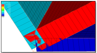
- Scaling at corners [0,10]
- Enter a scaling factor to use when interpolating thickness values near
t-junctions or corners. A value less than 1 will result in linear
decrease in the thickness values nearer to the junction/corners. A value
of zero will result in an approximate mass-conserved thickness
estimation. When equal to 1, the thickness is extrapolated /
interpolated without any scaling. When greater than 1, the thickness
will increase as you go closer to the junction.
Figure 8. Scaling = 0, Thickness Contour Applied, Traditional Element Visualization 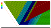
Figure 9. Scaling = 0, Thickness Contour Applied, 2D Detailed Element Representation 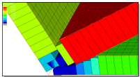
Figure 10. Scaling = 1, Thickness Contour Applied, Traditional Element Visualization 
Figure 11. Scaling = 1, Thickness Contour Applied, 2D Detailed Element Representation