Automatically generate a mesh at the midplane location, directly from the input
geometry (components, elements, solids or surfaces), without first creating a
midsurface.
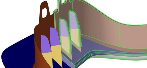
The midmesh functionality in HyperMesh saves significant
time over the traditional midsurface-based approach.Figure 1. Midmesh Result Example
The resulting output consists of 2D shell elements created with the user-provided
target size, as well as 1D elements defining the topology of the mesh
(vertices/edges/faces). Midmesh generation is also multithreaded to take advantage
of multi-core environments.
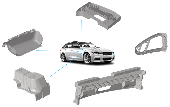
Direct Midmesh Supported Parts
Direct midmesh is supported for a large majority of parts including cast, machined,
injection molded and extruded as shown in Figure 2.Figure 2. Direct Midmesh Supported Parts
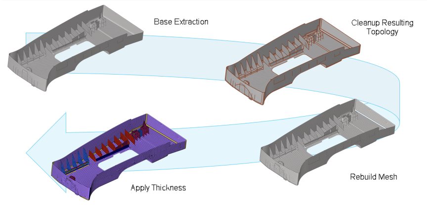
Midmesh Generation Workflow
There are several steps involved in generating a good quality midmesh. Following the
workflow shown in Figure 3 helps guarantee the best result with minimal manual effort.
Base Extraction
Extract the base midmesh.
Cleanup Resulting Topology
Use the semi-automated midmesh editing tools to correct the 1D topology
and fix any bad/missing faces. The goal is to prepare the model for
final remeshing.
Rebuild Mesh
Remesh to the final flow and quality using the rebuild mesh
functionality, and correct any remaining mesh quality issues.
Apply Thickness
Map the thickness from the original solid to the midmesh via the
Map Thickness tool.