Tetra Meshing
In this tutorial, you will learn to create tetra meshes using several different methods and tools.
Before you begin, copy the file(s) used in this tutorial to your
working directory.
In this tutorial you will:
- Fix the topology of a model to allow for tetra meshing
- Create a tetra mesh
- Create a tetra mesh using proximity and curvature settings
- Perform defeaturing operations to improve the quality of a tetra mesh
- Recreate the tetra mesh after defeaturing
- Create a tetra mesh using a shell mesh as an input
- Create a tetra mesh using Mesh Controls
- Detect features for Mesh Controls
Fix Topology
In this step, you will open the model and fix its topology to allow for tetra meshing.
- Start HyperMesh.
- From the menu bar, click .
-
Browse to your working directory, select
VOLUME-TETRA-MESH.hm, and click
Open.
The model opens in the modeling window.
Figure 1. 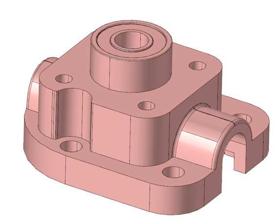
-
From the 2D ribbon, select the tool.
Figure 2. 
The model is displayed with its edges highlighted in green and red.Figure 3. 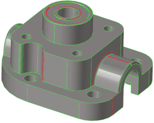
Note: The edges highlighted in red represent free edges, while those highlighted in green represent closed edges. -
From the guide bar, click
 .
.
- Under Free edges, set Stitch Tolerance to 0.1.
- Select all surfaces using and click Find on the guide bar.
-
From the guide bar, click
 to fix the
identified problems.
The legend now shows that there are three Free edges remaining.
to fix the
identified problems.
The legend now shows that there are three Free edges remaining.Figure 4. 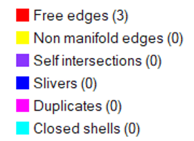
-
From the 2D ribbon, select the tool.
Figure 5. 
-
From the guide bar, click
 and
and  to navigate between the remaining free edges.
-
From the microdialog, click
 and click on the edge shown in Figure 6 to patch it.
Figure 6. 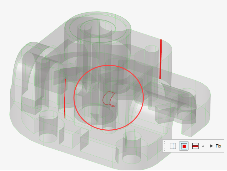
-
From the microdialog, click
 and select
  .
.
-
Set the Tolerance to 0.5 and click on the next
highlighted free edge shown in Figure 7 to fix it.
Figure 7. 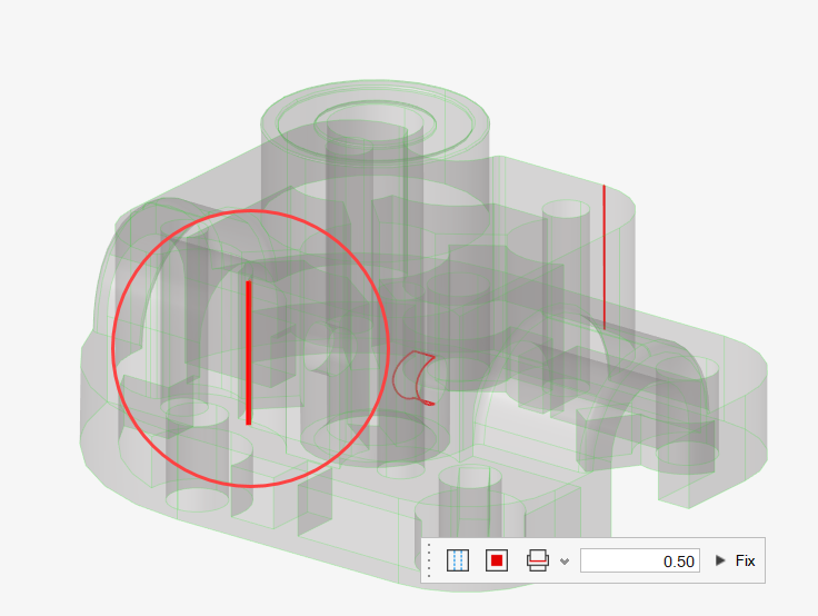
-
Click on the last highlighted free edge shown in Figure 8 to stitch it.
Figure 8. 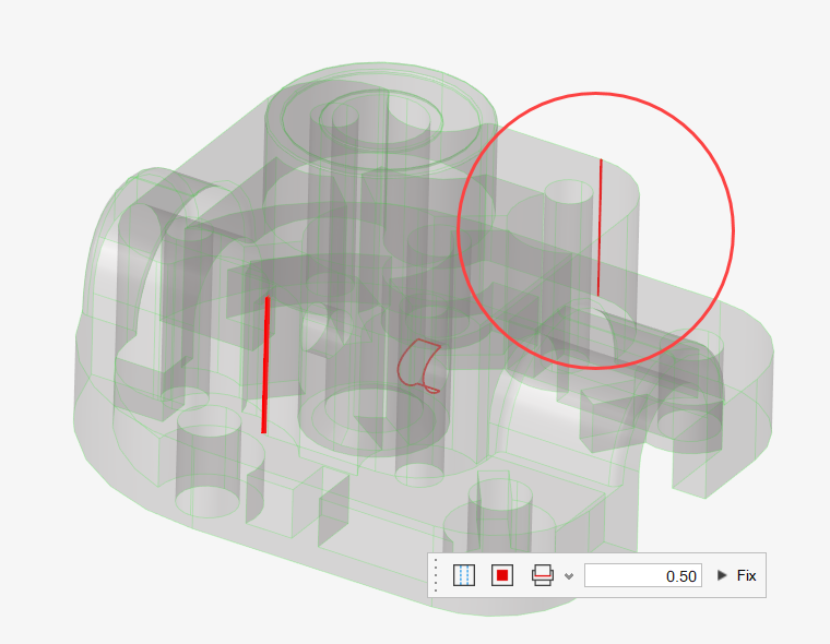
All edges are now highlighted in green.Figure 9. 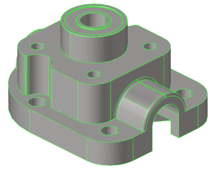
-
From the 2D ribbon, select the tool.
Figure 10. 
-
From the guide bar, click to create
the solid geometry.
Figure 11. 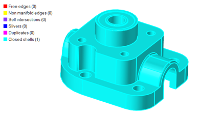
Create Tetra Mesh
In this step, you will create and review a tetra mesh.
-
From the 3D ribbon, select the tool.
Figure 12. 
- From the guide bar, select Solids from the drop-down menu.
- In the modeling window, select the model.
-
From the guide bar, click and set Average size to 4.
- Set Element order to Second.
- Verify that is set to Original component.
-
From the guide bar, click
Mesh.
Figure 13. 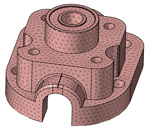
-
From the view controls toolbar, click
 and
set it to display Elements only.
and
set it to display Elements only.
-
Review the tetra mesh to identify areas for improvement.
Tip: Use
to display Geometry again to assist in identifying areas in need of
improvement.
Figure 14. 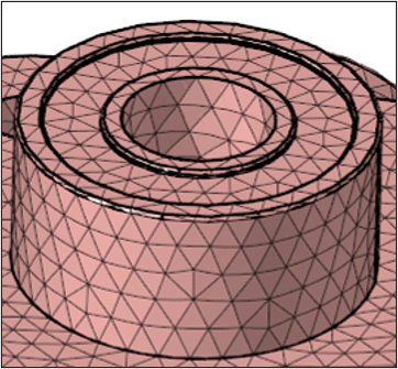
As seen in Figure 14, some areas of the tetra mesh still need fine-tuning.
- Right-click elements to be deleted and select Delete from the context menu.
Create Tetra Mesh Using Proximity and Curvature
In this step, you will create a tetra mesh using proximity and curvature settings.
- Use the right-click context menu to delete the previously created elements.
-
From the 3D ribbon, select the tool.
Figure 15.
- From the guide bar, select Solids from the drop-down menu.
- From the modeling window, click the model to select it.
-
From the guide bar, click and set Average size to 4.
- Set Element order to Second.
- Select the Use proximity and Curvature based refinement check boxes.
- Set Minimum size factor to 0.2 and set Feature angle to 30.
- Verify that Grow rate is set to 1.3.
- From the guide bar, click Mesh.
-
Review the tetra mesh that was created.
Note: Some areas need a topology defeaturing to produce a better mesh.
Figure 16. 
Perform Defeaturing Operations to Improve Tetra Mesh
In this step, you will use defeaturing operations to improve the quality of the tetra mesh.
- Use the right-click context menu to delete the previously created elements.
-
From the Topology ribbon, select the tool.
Figure 17. 
-
From the guide bar, click .
- Set Minimum to 0.001 and Maximum to 1 to identify only the fillet around the top hole.
- On the guide bar, click Find.
- On the guide bar, click Remove All.
-
From the Topology ribbon, select the tool.

-
Split the fillets as shown in Figure 18 by clicking and
dragging on the surface of the model.
Figure 18. 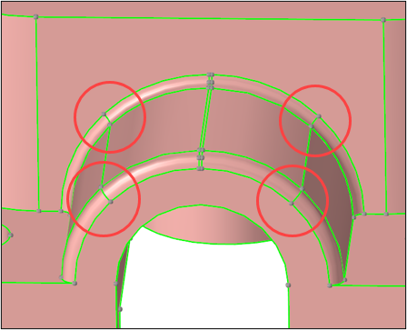
- Repeat for the other side.
-
From the Topology ribbon, select the
Suppress tool from the Stitch tool group.
Figure 19. 
-
Suppress the edges as shown in Figure 20 by clicking on
them.
Figure 20. 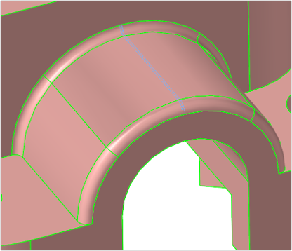
- Repeat for the other side of the model.
-
Inspect the model and suppress unnecessary shared edges as shown in Figure 21.
Figure 21. 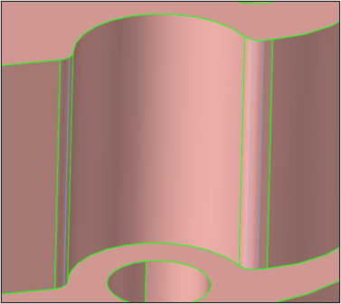
Recreate Tetra Mesh After Defeaturing
In this step, you will create an improved tetra mesh from the defeatured model.
-
From the 3D ribbon, select the tool.
Figure 22.
- From the guide bar, select Solids from the drop-down menu.
-
From the guide bar, click and set Average size to 4.
- Set Element order to Second.
- Select the Use proximity and Curvature based refinement check boxes.
- Set Minimum size factor to 0.2 and set Feature angle to 30.
- Select the Layered tetra check box and verify Number of layers is set to 2.
-
From the guide bar, click
Mesh.
Figure 23. 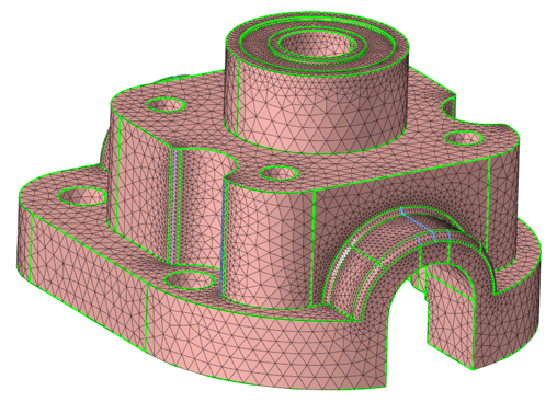
Create Tetra Mesh Using Shell Mesh as Input
- Delete the displayed elements.
-
From the 2D ribbon, click next to the BatchMesher tool
and select the Freeform tool from the drop-down menu.
The Create tool is selected by default from the Freeform sub-ribbon.
Figure 24. 
-
Select the surfaces shown in Figure 25.
Figure 25. 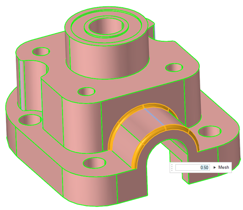
-
From the guide bar, click .
- Set Element size to 0.5.
- Set Element type to R-Trias.
- Set Element order to First.
- From the guide bar, click Mesh.
-
From the 2D ribbon, use the tool to adjust the density if necessary.
Figure 26. 
Figure 27. 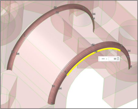
- Close the tool and examine the shell mesh just created.
- Repeat on the other side of the model.
-
From the 2D ribbon, select the tool.
Figure 28.
-
Select the surfaces shown in Figure 29 and Figure 30.
Figure 29. 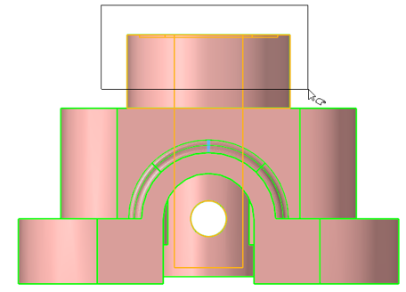
Figure 30. 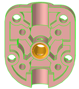
-
From the guide bar, click .
- Set Element size to 1.
- Set Element type to R-Trias.
- Set Element order to First.
- From the guide bar, click Mesh.
-
From the 2D ribbon, use the tool to check the density.
Figure 31. 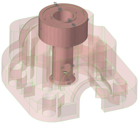
-
From the 3D ribbon, select the tool.
Figure 32.
- From the modeling window, select the solid.
-
From the guide bar, click .
- Set Average size to 4.
- Set Element order to First.
- Verify that the Retain existing surface mesh check box is selected.
- Select the Use proximity and Curvature based refinement check boxes.
- Set Minimum size factor to 0.2 and set Feature angle to 30.
- Select the Layered tetra check box and verify Number of layers is set to 2.
- From the guide bar, click Mesh and exit the tool.
- From the entity selector, select Elements.
- Press the Comma key and select Config from the context menu.
- Press to select all elements.
- Press the Period key to open the Select Elements dialog.
-
Clear the CTETRA check box and click OK.
Figure 33. 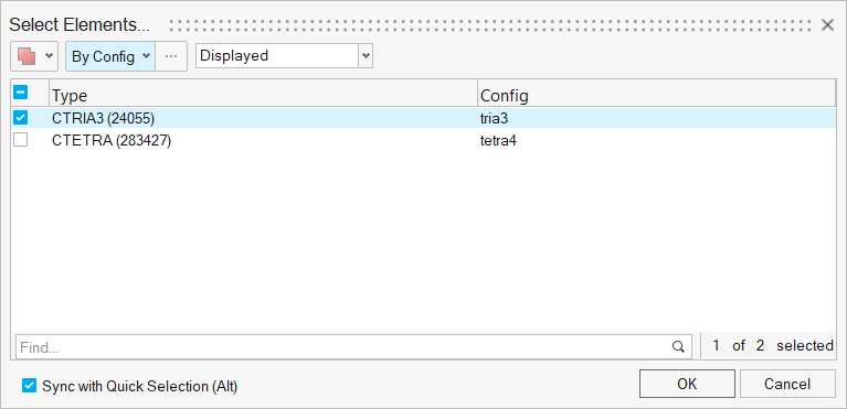
-
Right-click in the modeling window to open the context menu and select
Delete.
Figure 34. 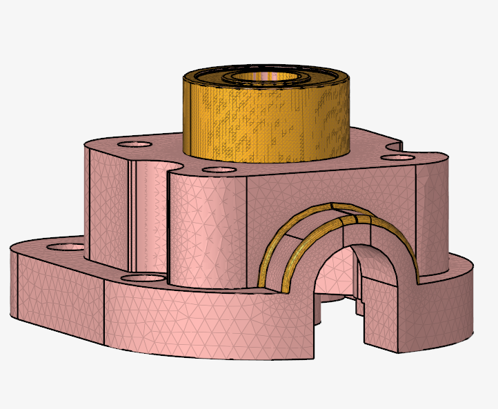
-
From the view controls toolbar, click and
set it to display Elements only.
- Review the final mesh.
Create Tetra Mesh With Mesh Controls
In this step, you will use mesh controls to create a tetra mesh.
-
From the View Controls toolbar, click and
enable Geometry view again.
- Use the right-click context menu to delete the previously created elements.
-
From the Topology ribbon, select the Mesh
Controls tool.

-
Create a model mesh control.
- In the Mesh Controls Browser, right-click on Surface Mesh and select .
- In the Entity Selection area of the Entity Editor, click Entities and select all surfaces of the model in the modeling window or press .
- In the Mesh Mode area of the Entity Editor, verify Mode is set to Surface Deviation.
- In the Main section of the Entity Editor, set Minimum Size to 0.8 and Maximum Size to 10.
- Set Element Type to Trias.
-
Create a local mesh control.
-
In the Entity Selection area of the Entity Editor, click Entities and select only the top
surface of the model in the modeling window as
shown in Figure 35.
Figure 35. 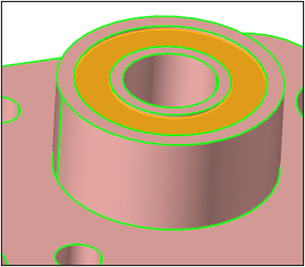
-
In the Entity Selection area of the Entity Editor, click Entities and select only the top
surface of the model in the modeling window as
shown in Figure 35.
-
Create an angle-based refinement mesh control.
- From the Mesh Controls Browser, right-click on Surface Mesh and select .
- In the Entity Selection area of the Entity Editor, click Entities and select all surfaces of the model in the modeling window or press .
- In the Refinement section of the Entity Editor, verify Direction is set to Convex.
- In the Refinement section of the Entity Editor, set Minimum Angle Limit to 30 and Maximum Angle Limit to 180.
- Set Refinement Size for Minimum Angle Limit and Maximum Angle Limit to 1.
-
Create a volume mesh control.
-
From the Entity Selection section of the Entity Editor, set Entities to the engine mount
component of the model.
Figure 36. 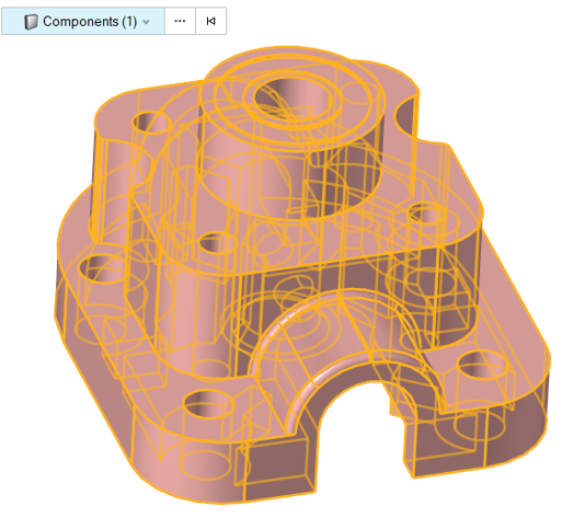
-
From the Entity Selection section of the Entity Editor, set Entities to the engine mount
component of the model.
- From the Mesh Controls Browser, right-click on Surface Mesh and select Mesh.
- From the Mesh Controls Browser, right-click on Volume Mesh and select Mesh.
-
Delete the previously created shell mesh (CTRIA3) and review the mesh.
Figure 37. 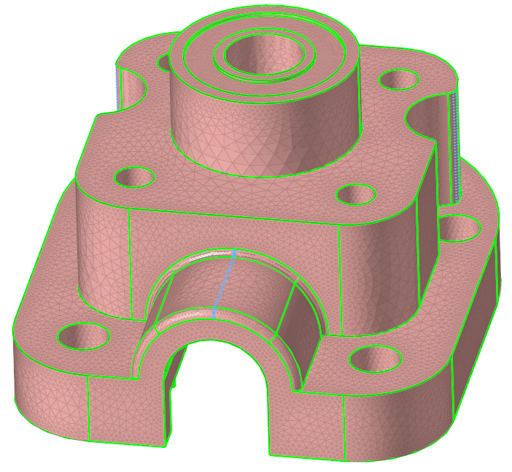
Detect Features for Mesh Controls
- Delete the displayed elements.
-
From the Topology ribbon, select the
Features tool.

-
In the Feature Detection Parameters dialog, define
parameters.
- Select only the Holes 3D and Fillets boxes, as shown in Figure 38.
- Set the Minimum Radius for Fillets to 1 and Maximum Radius to 5
- Click Find.
Figure 38. 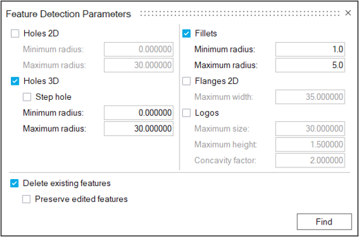
-
From the View Controls toolbar, click
 and select Features.
- Review the selected features and close the Feature Manager dialog.
-
From the Topology ribbon, select the Mesh
Controls tool.
Figure 39.
- In the Mesh Controls Browser, clear the Local, Model, and Refinement mesh controls check boxes to disable them.
-
Create a cylinder feature mesh control.
-
From the Entity Selection area of the Entity Editor, select the Entities field and click
 to open the Select
Surfaces dialog.
to open the Select
Surfaces dialog.
-
From the Select Surfaces dialog, select the
model's holes, as shown in Figure 40,
and click OK.
Figure 40. 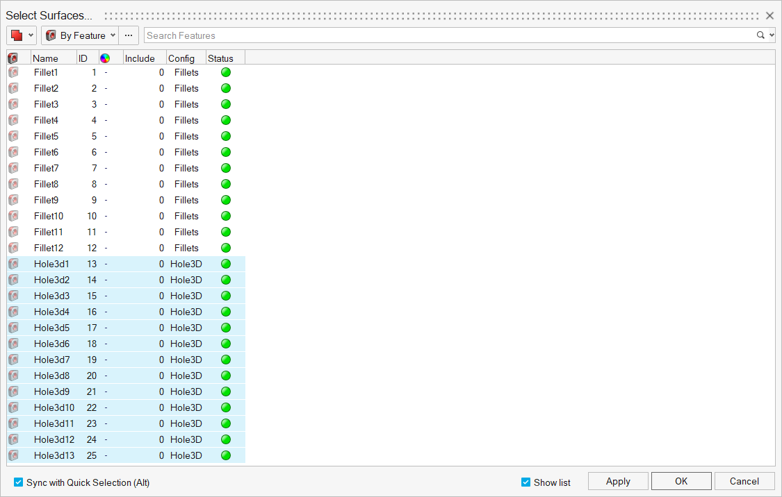
-
From the Entity Selection area of the Entity Editor, select the Entities field and click
-
Create a fillet mesh control.
-
From the Entity Selection area of the Entity Editor, select the Entities field and click
.
-
From the Select Surfaces window, select the
model's fillets, as shown in Figure 41,
and click OK.
Figure 41. 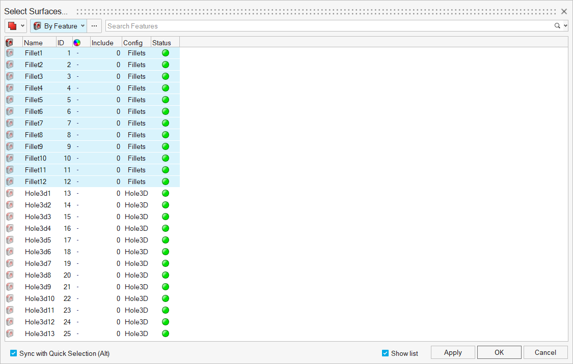
-
From the Entity Selection area of the Entity Editor, select the Entities field and click
-
Create a body feature mesh control.
-
From the Entity Selection area of the Entity Editor, click Entities
and, in the modeling window, select the engine
mount component.
Figure 42.
-
From the Entity Selection area of the Entity Editor, click Entities
and, in the modeling window, select the engine
mount component.
-
Create a washer feature mesh control.
-
From the Entity Selection section of the Entity Editor, set Entities to the highlighted lines
shown in Figure 43.
Figure 43. 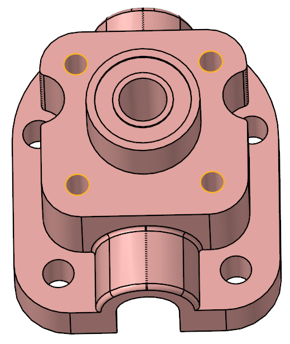
-
From the Entity Selection section of the Entity Editor, set Entities to the highlighted lines
shown in Figure 43.
- From the Mesh Controls Browser, right-click on Feature and select Mesh.
-
Review the surface mesh that was created.
Figure 44. 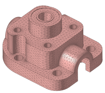
- From the Mesh Controls Browser, right-click on Volume Mesh and select Mesh.
- Delete the shell elements that were created before (CTRIA3).