Open Loop Events
In this tutorial, you will learn how to add an Altair Driver to the car model and to perform full vehicle simulations using open loop maneuvering event scripts.
The Altair Driver is a set of MotionView models and libraries that allow for the control and scripting of vehicle events.
Event examples include the following:
- Constant radius cornering
- Single lane change
- Double lane change
- User defined path following
- Fish hook event, and so on.
This is achieved by creating an interface to the five vehicle inputs:
- Steering
- Throttle
- Gear
- Brake
- Clutch
You can use the Altair Driver to simulate any number of full vehicle events using multiple features:
- Scripting: break up the simulation into different maneuvers; select the controllers for vehicle inputs and define conditions that end each maneuver.
- Open-loop, closed-loop, and user-defined controllers to control.
- Longitudinal speed or acceleration.
- Vehicle path or lateral acceleration.
- Switching controllers during a simulation.
- Defining path and speed profiles parametrically, in a table, or by referencing a data file.
Load the Vehicle
In this step, you will load the tutorial car model.
- Start a new MotionView session.
- From the menu bar, select to open the Extensions dialog.
-
From the Extensions dialog, enable the Vehicle Tools
extension by clicking the toggle slider under Vehicle Tools.
The Vehicle Tools extension is responsible for the proper functionality of the Driver.
Figure 1. Loading Vehicle Tools Extension 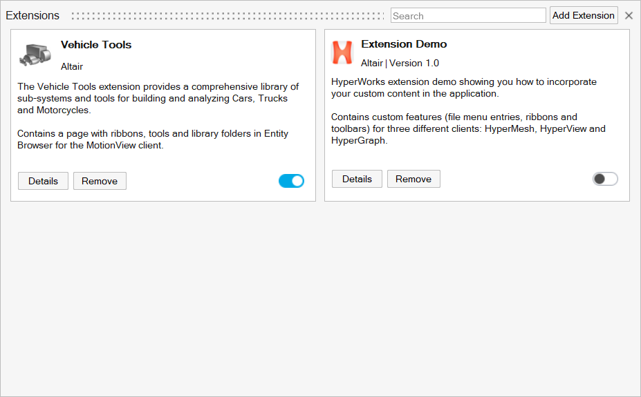
-
Click
 to close the
Extensions dialog.
to close the
Extensions dialog.
- From the menu bar, select and select Car_model.mdl.
Add Altair Driver
In this step, you will use the Vehicle Tools Components to load the driver.
- From the menu bar, select to open the Entity Browser.
- From the Entity Browser, select .
-
Double-click on Driver.
Figure 2. 
- From the guide bar, verify that Vehicle Body is highlighted.
- From the modeling window, select the Vehicle Body part.
- Select the Road Reference Marker Front-left marker.
-
From the microdialog, select
Create.
The Altair Driver is added to the car model and all attachments are auto-resolved, which can be seen in driver entity editor.
Add Altair Driver File
- From the Entity Browser, select .
-
Double-click the DriverFile icon
 to add a new
driver file to the model.
to add a new
driver file to the model.
Figure 3. Altair Driver File on Entity Editor 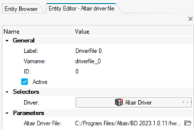
The Altair Driver File selection is located under the Parameters section.
Figure 4. Altair Driver Selection 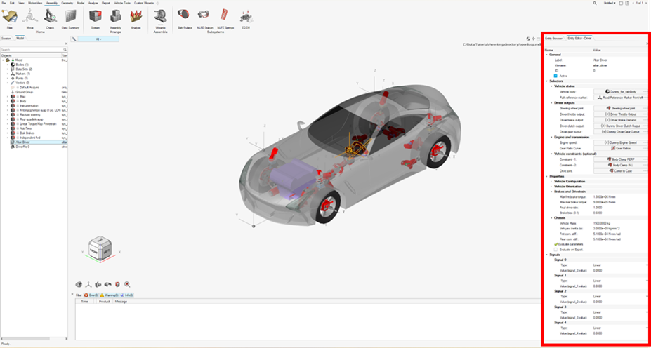
The Altair Driver is added to the Model Browser.
Create an Altair Driver File Driving Event
In this step, you will script an event with 50% throttle, 0% brake, and 0 steering angle.
Driver requires an event script or the Altair driver file (ADF) to run any driving event. The ADF can be edited using any text editor or by clicking the View/Edit button on the Altair Driver File Entity Editor. An event can be broken down into smaller sub-events or maneuvers. You will model this as a single maneuver event.
-
Open any text editor and copy the following text into it:
$-----------------------------------------------------------------ALTAIR_HEADER
$ This block is required for version control
[ALTAIR_HEADER]
FILE_TYPE 		= 'ADF'
FILE_VERSION 	= 2.0
FILE_FORMAT 	= 'ASCII'
$--------------------------------------------------------------------------UNITS
$In this block we specify the units in which this file should be read
[UNITS]
(BASE)
{length  force      	angle       mass   time}
'meter'   'newton'   	'radians'  'kg'      'sec'
$--------------------------------------------------------------------VEHICLE_IC
$In this block we specify the initial conditions specifically initial speed of the
$vehicle with respect to the vehicle IC marker in the driver attachments
[VEHICLE_INITIAL_CONDITIONS]
VX0 = 20.0
VY0 = 0.0
VZ0 = 0.0
$--------------------------------------------------------------STEERING_STANDARD
$This block specifies the saturation and cutoff frequency for the low pass filter for
$steering output signal. These signals are global and are active for the entire event
[STEER_STANDARD]
MAX_VALUE 			= 3.141593
MIN_VALUE 			= -3.141593
SMOOTHING_FREQUENCY 	= 10.0
INITIAL_VALUE 		= 0.0
$--------------------------------------------------------------THROTTLE_STANDARD
$This block specifies the saturation and cutoff frequency for the low pass filter for
$throttle output signal
[THROTTLE_STANDARD]
MAX_VALUE 			= 1.0
MIN_VALUE 			= 0.00
SMOOTHING_FREQUENCY 	= 10.0
INITIAL_VALUE 		= 0.5
$---------------------------------------------------------------BRAKING_STANDARD
$This block specifies the saturation and cutoff frequency for the low pass filter for
$brake output signal
[BRAKE_STANDARD]
MAX_VALUE 			= 1.0
MIN_VALUE 			= 0.0
SMOOTHING_FREQUENCY 	= 10.0
INITIAL_VALUE 		= 0.0
$-----------------------------------------------------------------MANEUVERS_LIST
$This block provides the list of all the maneuvers, simulation time for each maneuver
$maximum solver step size (hmax) and print interval
[MANEUVERS_LIST]
{ name       		simulation_time  h_max  print_interval}
'MANEUVER_1'	5.0                     0.01     0.01
$---------------------------------------------------------------------MANEUVER_1
[MANEUVER_1]
$This block provides the ties controllers to each driver output
TASK = 'STANDARD'
(CONTROLLERS)
{DRIVER_SIGNAL  	PRIMARY_CONTROLLER 	ADDITIONAL_CONTROLLER}
STEER                   	OL_STEER_0	  		NONE
THROTTLE             	OL_0.5	  		NONE
BRAKE                   	OL_0	  			NONE
$---------------------------------------------------------OL_STEER
$This is controller block containing all the information required by
$the driver to construct the controller. Different controllers have
$different requirements. Here we are using open loop constant type
$of controller.
[OL_STEER_0]
TAG	= 'OPENLOOP'
TYPE	= 'CONSTANT'
VALUE	= 0.0
$---------------------------------------------------------OL_BRAKE
[OL_0]
TAG	= 'OPENLOOP'
TYPE	= 'CONSTANT'
VALUE	= 0.0
SMOOTHING = 'TRUE'
$---------------------------------------------------------OL_THROTTLE
[OL_0.5]
TAG	= 'OPENLOOP'
TYPE	= 'CONSTANT'
VALUE	= 0.5
SMOOTHING = 'TRUE'
Important: All blank lines must be removed prior to saving the file.Tip: Read through the comments for a better understanding of what is written in the ADF. - Save the file as openloop_acc.adf.
-
From the Parameter section of the Altair drive file's Entity Editor, click
 next to Altair Driver File.
-
From the Open File dialog, select the
openloop_acc.adf file.
Figure 6. 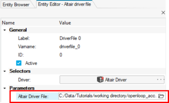
Note: The View/Edit button can be used to edit the file.Figure 7. View/Edit Altair Driver File 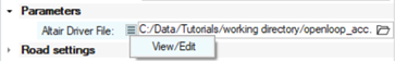
-
From the Vehicle Tools ribbon, select the Analysis
Settings tool from the Run tool group to open the Run
Motion Analysis dialog.
Figure 8. 
- From the Run Motion Analysis dialog, select the Run Offline check box.
- Set an Output directory of your preference.
- Click Run to initiate the analysis.
-
After the simulation is finished and the solver creates the
.h3d and .plt files, navigate to
the Vehicle Tools ribbon and select the Report
tool.
Figure 9. 
-
From the View Reports dialog, select the recent run and
click OK.
Figure 10. 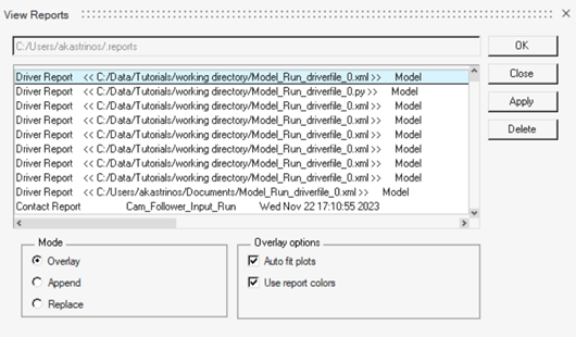
The noise in the steering is numerical error of negligible magnitude – 0 for all practical purposes. Throttle is constant at 0.5 (driver throttle, brake and clutch outputs are normalized so, 50%) and brake is constant at 0.Figure 11. Steering and Throttle Driver Inputs 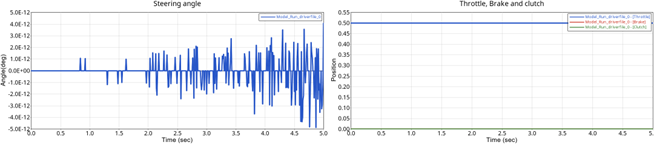
-
Next, try running it again with slightly different initial conditions by
changing the throttle and brake values.
-
From the Parameters section of the Altair driver file's Entity Editor, click
 next to Altair Driver File
and select View/Edit from the drop-down menu to
open the ADF file in a text editor.
next to Altair Driver File
and select View/Edit from the drop-down menu to
open the ADF file in a text editor.
-
From the Parameters section of the Altair driver file's Entity Editor, click
- Save the ADF.
-
From the Vehicle Tools ribbon, select the Analysis
Settings tool from the Run tool group to open the Run
Motion Analysis dialog.
Figure 12.
- From the Run Motion Analysis dialog, select the Run Offline check box.
- Set an Output directory of your preference.
- Click Run.
-
After the simulation is finished and the solver creates the
.h3d and .plt files, navigate to
the Vehicle Tools ribbon and select the Report
tool.
Figure 13.
-
From the View Reports dialog, select the recent run and
click OK.
Now the throttle and brake start from respective initial values and step up to the controller outputs. The time taken to step up is roughly (5x1/SMOOTHING_FREQUENCY).
Figure 14. Driver Outputs Using Different Initial Values. 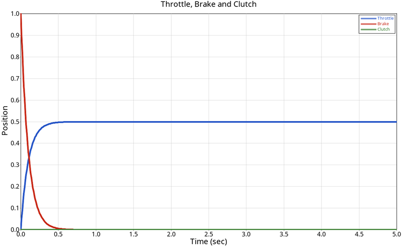
Model an Open Loop Sinusoidal Steering Event
In this step, you will model a simple event with constant 20% throttle, constant 0% throttle and sinusoidal steering input with amplitude of 60 degrees (∏/3 radians) and frequency of 0.5 Hz.
-
Open any text editor and copy and paste the following text into it.
Important: All blank lines must be removed prior to saving the file.
$-----------------------------------------------------------------ALTAIR_HEADER [ALTAIR_HEADER] FILE_TYPE = 'ADF' FILE_VERSION = 2.0 FILE_FORMAT = 'ASCII' $--------------------------------------------------------------------------UNITS [UNITS] (BASE) {length force angle mass time} 'meter' 'newton' 'radians' 'kg' 'sec' $--------------------------------------------------------------------VEHICLE_IC [VEHICLE_INITIAL_CONDITIONS] VX0 = 20.0 VY0 = 0.0 VZ0 = 0.0 $--------------------------------------------------------------STEERING_STANDARD [STEER_STANDARD] MAX_VALUE = 3.141593 MIN_VALUE = -3.141593 SMOOTHING_FREQUENCY = 10.0 INITIAL_VALUE = 0.0 $--------------------------------------------------------------THROTTLE_STANDARD [THROTTLE_STANDARD] MAX_VALUE = 1.0 MIN_VALUE = 0.00 SMOOTHING_FREQUENCY = 10.0 INITIAL_VALUE = 0.2 $---------------------------------------------------------------BRAKING_STANDARD [BRAKE_STANDARD] MAX_VALUE = 1.0 MIN_VALUE = 0.0 SMOOTHING_FREQUENCY = 10.0 INITIAL_VALUE = 0.0 $-----------------------------------------------------------------MANEUVERS_LIST [MANEUVERS_LIST] { name simulation_time h_max print_interval} 'MANEUVER_1' 10.0 0.01 0.01 $---------------------------------------------------------------------MANEUVER_1 [MANEUVER_1] $This block provides the ties controllers to each driver output TASK = 'STANDARD' (CONTROLLERS) {DRIVER_SIGNAL PRIMARY_CONTROLLER ADDITIONAL_CONTROLLER} STEER OL_STEER NONE THROTTLE OL_THROTTLE NONE BRAKE OL_BRAKE NONE $---------------------------------------------------------OL_STEER. $SIGNAL_CHANNEL tells the driver which solver variable in Signal Generator to over-ride $with the EXPRESSION value. The EXPRESSION should be consistent with MOTIONSOLVE. [OL_STEER] TAG = 'OPENLOOP' TYPE = 'EXPRESSION' SIGNAL_CHANNEL = 0 EXPRESSION = 'DTOR(60)*SIN(2*PI*0.5*TIME)' $---------------------------------------------------------OL_THROTTLE [OL_THROTTLE] TAG = 'OPENLOOP' TYPE = 'CONSTANT' VALUE = 0.2 $---------------------------------------------------------OL_BRAKE [OL_BRAKE] TAG = 'OPENLOOP' TYPE = 'CONSTANT' VALUE = 0.0 - Save the file as openloop_sin.adf.
-
From the Parameter section of the Altair drive file's Entity Editor, click
next to Altair Driver File.
- From the Open File dialog, select the openloop_sin.adf file.
-
From the Vehicle Tools ribbon, select the Analysis
Settings tool from the Run tool group to open the Run
Motion Analysis dialog.
Figure 15.
- From the Run Motion Analysis dialog, select the Run Offline check box.
- Set an Output directory of your preference.
- Click Run to initiate the analysis.
-
After the simulation is finished and the solver creates the
.h3d and .plt files, navigate to
the Vehicle Tools ribbon and select the Report
tool.
Figure 16.
-
From the View Reports dialog, select the recent run and
click OK.
Figure 17. Driver Outputs in an Open Loop Sinusoidal Steering Event 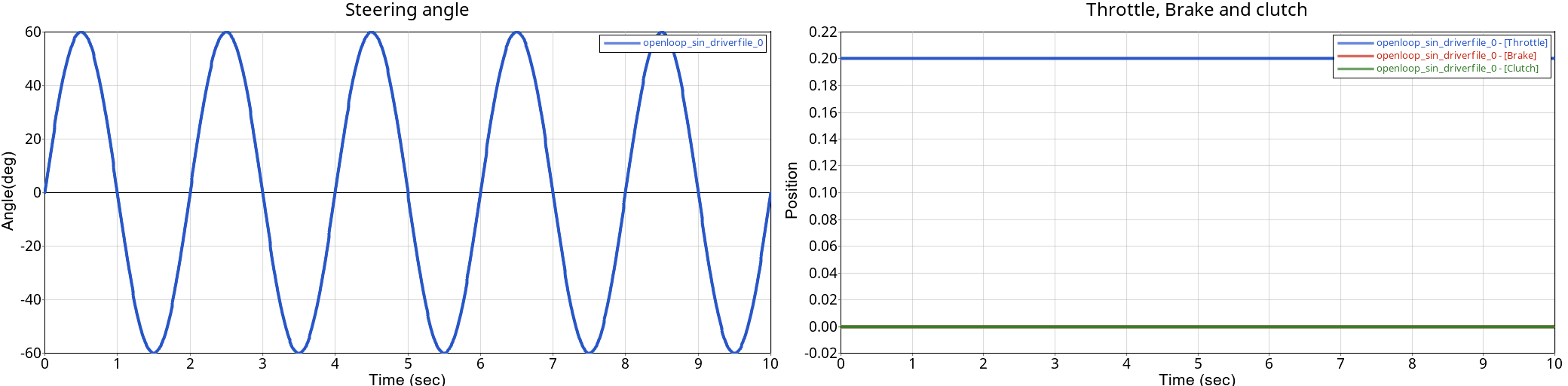
Model an Open Loop Curve Driven Braking Event
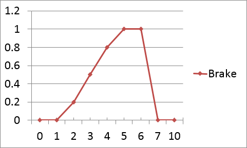
In this step, you will model a simple event with a braking signal as a curve.
-
Open any text editor and copy and paste the following text into it.
Important: All blank lines must be removed prior to saving the file.
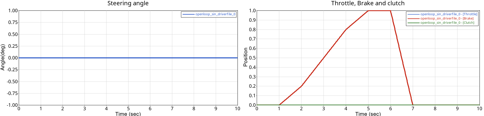
$-----------------------------------------------------------------ALTAIR_HEADER [ALTAIR_HEADER] FILE_TYPE = 'ADF' FILE_VERSION = 2.0 FILE_FORMAT = 'ASCII' $--------------------------------------------------------------------------UNITS [UNITS] (BASE) {length force angle mass time} 'meter' 'newton' 'radians' 'kg' 'sec' $--------------------------------------------------------------------VEHICLE_IC [VEHICLE_INITIAL_CONDITIONS] VX0 = 20.0 VY0 = 0.0 VZ0 = 0.0 $--------------------------------------------------------------STEERING_STANDARD [STEER_STANDARD] MAX_VALUE = 3.141593 MIN_VALUE = -3.141593 SMOOTHING_FREQUENCY = 10.0 INITIAL_VALUE = 0.0 $--------------------------------------------------------------THROTTLE_STANDARD [THROTTLE_STANDARD] MAX_VALUE = 1.0 MIN_VALUE = 0.00 SMOOTHING_FREQUENCY = 10.0 INITIAL_VALUE = 0.0 $---------------------------------------------------------------BRAKING_STANDARD [BRAKE_STANDARD] MAX_VALUE = 1.0 MIN_VALUE = 0.0 SMOOTHING_FREQUENCY = 10.0 INITIAL_VALUE = 0.0 $-----------------------------------------------------------------MANEUVERS_LIST [MANEUVERS_LIST] { name simulation_time h_max print_interval} 'MANEUVER_1' 10.0 0.001 0.01 $---------------------------------------------------------------------MANEUVER_1 [MANEUVER_1] $This block provides the ties controllers to each driver output TASK = 'STANDARD' (CONTROLLERS) {DRIVER_SIGNAL PRIMARY_CONTROLLER ADDITIONAL_CONTROLLER} STEER OL_STEER NONE THROTTLE OL_THROTTLE NONE BRAKE OL_BRAKE NONE $---------------------------------------------------------OL_STEER. $SIGNAL_CHANNEL tells the driver which solver variable in Signal Generator to over-ride $with the EXPRESSION value. The EXPRESSION should be consistent with MOTIONSOLVE. [OL_STEER] TAG = 'OPENLOOP' TYPE = 'CONSTANT' VALUE = 0.0 $---------------------------------------------------------OL_THROTTLE [OL_THROTTLE] TAG = 'OPENLOOP' TYPE = 'CONSTANT' VALUE = 0.0 $---------------------------------------------------------OL_BRAKE [OL_BRAKE] TAG = 'OPENLOOP' TYPE = 'CURVE' BLOCK = 'BRAKE_CRV' $---------------------------------------------------------CURVE_DATA [BRAKE_CRV] INDEPENDENT_VARIABLE = 'TIME' DEPENDENT_VARIABLE = 'BRAKE_SIGNAL' INTERPOLATION = 'LINEAR' {TIME BRAKE_SIGNAL} 0 0 1 0 2 0.2 3 0.5 4 0.8 5 1.0 6 1.0 7 0 10 0 - Save the file as openloop_brake.adf.
-
From the Parameter section of the Altair drive file's Entity Editor, click
next to Altair Driver File.
- From the Open File dialog, select the openloop_brake.adf file.
-
From the Vehicle Tools ribbon, select the Analysis
Settings tool from the Run tool group to open the Run
Motion Analysis dialog.
Figure 19.
- From the Run Motion Analysis dialog, select the Run Offline check box.
- Set an Output directory of your preference.
- Click Run to initiate the analysis.
-
After the simulation is finished and the solver creates the
.h3d and .plt files, navigate to
the Vehicle Tools ribbon and select the Report
tool.
Figure 20.
-
From the View Reports dialog, select the recent run and
click OK.
Figure 21. Driver Outputs in an Open Loop Curve Driven Braking Event