Use the Ribs tool to create and modify simple ribs between two surfaces.
Geometry definition is normally created in CAD systems and imported into the HyperMesh database. CAE modeling is done using the geometry
available in HyperMesh. From the CAE analysis results or
from optimization of the structures, sometimes it is necessary to add stiffening
ribs to the geometry. It is not convenient to use the CAD system to add ribs and
modify the dimensions or locations. Using this tool, you can create and modify
simple ribs between two surfaces, but not more than two surfaces. Complicated ribs
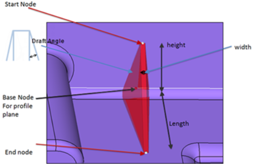
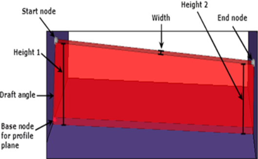
still need to be created in the CAD system and re-imported into HyperMesh.Figure 1. Triangular Rib Terminology Figure 2. Quadrilateral Rib Terminology
From the Topology ribbon, click the arrow next to the
Create tool set name and select Ribs.
Select the rib position from the profile plane (centered, on right,
or on left).
Rib Start Node
Select a rib start node on a surface where the rib will start. You
can modify this during the preview. This will give the height of the
rib.
Rib End Node
Select a rib end node on a surface where the rib will end. You can
modify this during the preview. This will give the length of the
triangular rib or the height at the other end of the quadrilateral
rib.
Reference Node
Define the location and orientation of the rib. This node is used as
reference geometry, with respect to which sides of the rib are
constructed. For example, when draft angle is zero, the two side
surfaces of the rib are parallel to this plane.
Height 1 and Height 2
Specify height 1 and height 2 of the quadrilateral rib. Provides
heights at both ends for the quadrilateral rib.
Height and Length
Specify the height and length of the triangular rib.
Width
Specify the width of the rib.
Draft Angle
Specify an angle used for the side face inclination.