MV-1029: Model a Point-to-Deformable-Surface Force (PTdSF)
In this tutorial you will learn how to model a PTdSF (point-to-deformable-surface) joint with a contact force.
Create Points
In this step you will create the points necessary for the PTdSF force model.
- Start a new MotionView session.
-
Open the Add Point or PointPair dialog in one of the
following ways:
- From the Project Browser right-click on Model and select .
- On the Model-Reference toolbar, right-click the
 (Point) icon.
- For Label, enter BallCM. Accept the default Variable name.
- Click OK.
- Click the Properties tab and specify the coordinates as X=0.0, Y=0.0, and Z=50.0.
-
Repeat steps 2
through 5 for the
points specified in Table 1.
Table 1. Point X Y Z PointMembInterface39 -55.0 -55.0 0.0 PointMembInterface40 55.0 -55.0 0.0 PointMembInterface41 55.0 55.0 0.0 PointMembInterface42 -55.0 55.0 0.0
Create Bodies
In this step, you will create membrane and ball bodies for the PTdSF force model.
-
Open the Add Body or BodyPair dialog in one of the
following ways:
- From the Project Browser right-click on Model and select .
- On the Model-Reference toolbar, right-click on the
 (Body) icon.
-
In the dialog, for Label enter Membrane. Accept the
default Variable name and click OK.
Note: For the remainder of the tutorial, accept all default variable names.
- From the Properties tab, click the Flex Body (CMS) check box.
-
Click the
 (Graphic file browser) icon and select
Plate.h3d from the <working
directory>.
(Graphic file browser) icon and select
Plate.h3d from the <working
directory>.
- Repeat step Table 2. In the dialog, for Label enter Ball.
-
From the Properties tab, specify the information provided in Table 2.
Table 2. Mass Ixx Iyy Izz Ixy Iyz Izx 1 40000.0 40000.0 40000.0 0.0 0.0 0.0 - Under the CM Coordinates tab, check the Use center of mass coordinate system box.
-
Double click
 .
.
- From the dialog, select BallCM and click OK. Accept defaults for axes orientation properties.
Create Markers and a Deformable Surface
In this step you will define markers for the membrane.
-
On the general toolbar, click .
Figure 1. 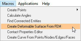
-
In the Deformable Surface from FEM panel, double-click
 .
.
- From the dialog, select Membrane and click OK.
-
Double-click on
 .
.
- From the dialog, choose Model and click OK.
-
Next to Select the FEM file, click the (file
browser) icon.
-
Select the membrane.fem file from your working directory
and click OK.
Figure 2. 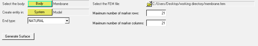
-
Click Generate Surface.
The Markers and Deformable Surface are created.
Create Joints
In this step you will define the fixed joints between the membrane and the ground.
-
Open the Add Joint or JointPair dialog in one of the
following ways:
- From the Project Browser, right-click on Model and select .
- On the Model-Constraint toolbar, click the
 (Joints) icon.
- In the dialog, for Label enter Joint 1.
- For Type, choose Fixed Joint and click OK.
-
In the Joint panel, configure the Connectivity tab.
-
Double-click
 .
.
- In the dialog, select Membrane and click OK.
-
Double-click
 .
.
- In the dialog, select Ground Body and click OK.
-
Double-click .
- In the dialog, select PointMembInterface39 and click OK.
-
Double-click
-
Repeat steps 1
through 4 using
the specifications given in Table 3.
Table 3. Label Joint Type Body 1 Body 2 Point Joint 2 Fixed Joint Membrane Ground Body PointMembInterface40 Joint 3 Fixed Joint Membrane Ground Body PointMembInterface41 Joint 4 Fixed Joint Membrane Ground Body PointMembInterface42
Create Contact
In this step you will define the contact force between the deformable membrane and the ball.
-
Open the Add Contact dialog in one of the following ways:
- From the Project Browser, right-click on Model and select .
- On the Model-Force toolbar, click the
 (Contacts) icon.
- In the dialog, for Label enter Contact 0.
- From the Type drop-down menu, choose PointToDeformableSurfaceContact. Then click OK.
-
From the Contact panel, configure the Connectivity tab.
-
Double-click on and select Ball.
Then click OK.
-
Double-click on and select BallCM.
Then click OK.
-
Double-click on
 and select DeformableSurface
1. Then click OK.
and select DeformableSurface
1. Then click OK.
-
Double-click on
-
Configure the Properties tab.
- For Radius, enter 10.
- For Stiffness, enter 1000.
- For Damping, enter 0.2.
- Uncheck the Flip normal check box.
Create Graphics
In this step, you will create a graphic for the ball.
-
Open the Add Graphics or GraphicPair dialog in one of the
following ways:
- From the Project Browser, right-click on Model and select .
- On the Model-Reference toolbar, click the
 (Graphics) icon.
- In the dialog, for Label enter Ball.
- In the Type drop-down menu, choose Sphere. Then click OK.
-
In the Connectivity tab, double-click .
- In the dialog, select Ball and click OK.
-
Double-click on .
- In the dialog, select BallCM and click OK.
- In the Properties tab, under Radius enter 10.
- In the Visualization tab, choose a color for the graphic.
Find Nodes
- In the Project Browser, click on the Membrane body.
-
On the reference toolbar, click the (Bodies) icon.
- In the panel, click the Nodes button.
- In the dialog, uncheck the Only search interface nodes box.
- Click the Find All button.
-
Close the dialog.
Your model should look like the example given in Figure 3.
Figure 3. 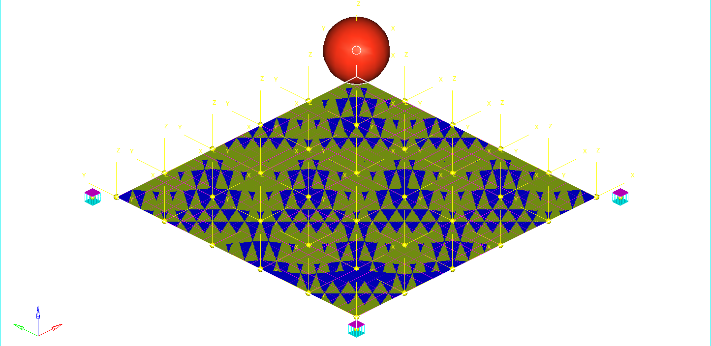
- Save the model as ptdsf_contact.mdl.
Run the Model
-
On the toolbar, click
 (Run).
-
In the Run panel, specify the values shown in Figure 4.
Figure 4. 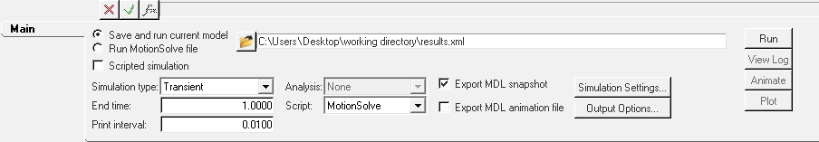
- Click the Save and run current model radio button.
-
Click the
 (browser icon) and specify
result.xml as the name for the solver file.
(browser icon) and specify
result.xml as the name for the solver file.
- Click Save.
-
Click the
 (Check Model) button to check the model for
errors.
(Check Model) button to check the model for
errors.
- To invoke the solver, click the Run button.
- Once the solver has finished, Close the solver window and Clear the Message Log.
View the Results
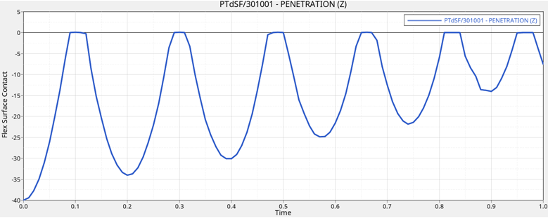
In this step, you will view the animation and plot the Z position of the center of mass of the ball and the penetration distance for this flexible contact.
-
Once the solver has finished, the Animate button will be active. Click on
Animate.
Click the
 (Start/Pause Animation) button
to view the animation.
(Start/Pause Animation) button
to view the animation.One would also like to inspect the displacement profile of the membrane and the ball. For this, we will plot the Z position of the center of mass of the ball.
-
Return to MotionView and in the Run panel, click
the Plot button.
This will open a HyperGraph window and load the results file.
-
In the panel, make selections for the plot as shown in Figure 5.
Figure 5. 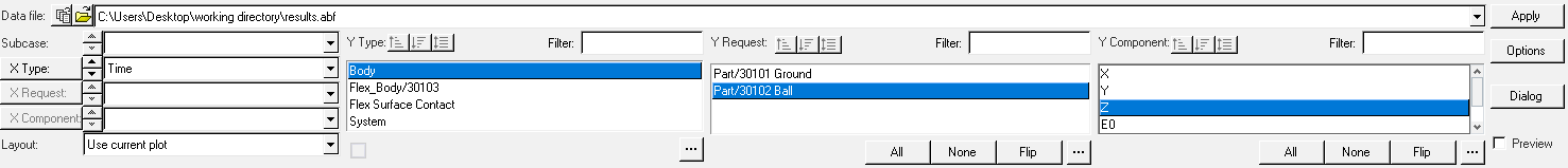
-
Click Apply.
The profile for the Z-displacement of the ball should look like the example given in Figure 6.
Figure 6. 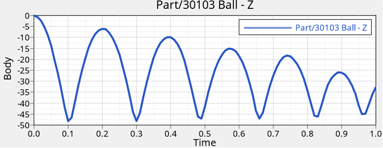
-
Click
 to add a new page to the session.
-
In the panel, select the options for the plot shown in Figure 7.
Figure 7. 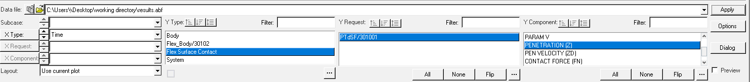
The penetration profile as a function of time should look like the example given in Figure 8.Figure 8.