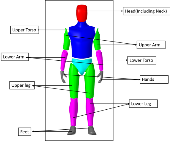
The Rider models the mass and inertia of a human body and includes graphics for the human
body. Controls for setting are available for modifying the mass, dimension of a human body,
and for changing the angles in joints. Changing the angles in joints allows positioning the
rider in many postures.
The Rider is not flexible: the bodies comprising the model and the joints connecting the
bodies are rigid.Figure 1. Rider model
Parameters
General Info
Position
Pre-defined positions are available to quickly position the Rider. Current options
are ‘Standing’, ‘Motorcycle Rider’, ‘Scooter Rider’, ‘Truck Driver’ and ‘Car
Driver’.
Height
The Rider height specified in centimeters. The height can vary from 100 to 200
cm.
Body Density
Specifies the body density in kg per meter cube.
Mass
Displays the mass of the Rider in the model units based on the specified height and
body density value. This parameter is not editable and is only used to demonstrate the
current Rider mass.
Inertia Ixx, Iyy, Izz
Displays the moment inertia values of the Rider in the model units based on the
height and body density values. This parameter is not editable and is only used to
demonstrate the current Rider inertia values.
Body Joint Angles
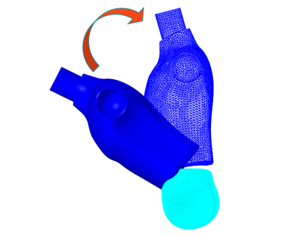
Pelvis (forward – backward)
Input for the pelvis angle about y direction.Figure 2.
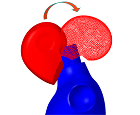
Neck (up – down)
Input for the neck angle about y direction.Figure 3.
Knee Symmetry
Check the box to mirror the values from left to right. It makes the right limb angle
field read only.
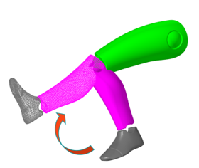
Left/Right Knee (fold – unfold)
Input for the left/right knee angle about y direction.Figure 4.
Ankle Symmetry
Check the box to mirror the values from left to right. It makes the right limb angle
field read only.
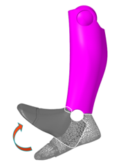
Left/Right Ankle (up – down)
Input for the left/right ankle angle about y direction.Figure 5.
Elbow Symmetry
Check the box to mirror the values from left to right. It makes the right limb angle
field read only.
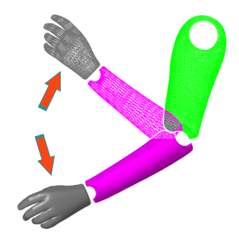
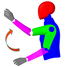
Left/Right Elbow (fold – unfold)
Input for the left/right elbow angle about y direction.Figure 6.
Hip Fold Symmetry
Check the box to mirror the values from left to right. It makes the right limb angle
field read only.
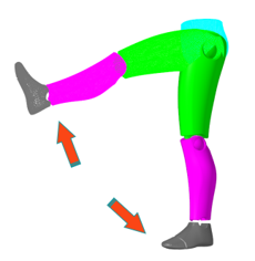
Left/Right Leg (fold – unfold)
Input for the left/right leg angle about y direction.Figure 7.
Hip Lateral Symmetry
Check the box to mirror the values from left to right. It makes the right limb angle
field read only.
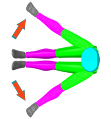
Left/Right Leg (fold – unfold)
Input for the left/right leg angle about x direction.Figure 8.
Hip Rotation Symmetry
Check the box to mirror the values from left to right. It makes the right limb angle
field read only.
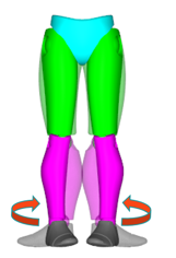
Left/Right Leg (in – out)
Input for the left/right leg angle about z direction.Figure 9.
Shoulder Fold Symmetry
Check the box to mirror the values from left to right. It makes the right limb angle
field read only.
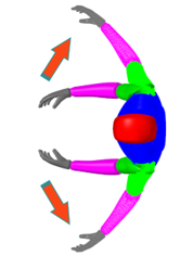
Left/Right Shoulder (fold – unfold)
Input for the left/right shoulder angle about y direction.Figure 10.
Shoulder Lateral Symmetry
Check the box to mirror the values from left to right. It makes the right limb angle
field read only.
Left/Right Shoulder (fold – unfold)
Input for the left/right shoulder angle about z direction.Figure 11.
Wrist Symmetry
Check the box to mirror the values from left to right. It makes the right limb angle
field read only.
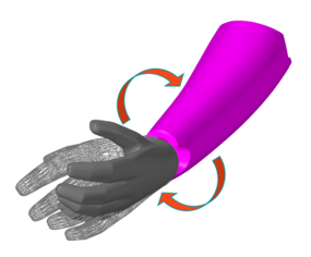
Left/Right Wrist (in – out)
Input for the left/right wrist angle about z direction.Figure 12.
Connecting a Rider
When adding a Rider the guide bar
appears showing the body and marker collectors.
From the guide bar, select the reference marker for the
Rider. The marker is used to locate the Rider and provides an initial frame of
reference.
Click on Reference Marker and select a marker
from the modeling window.
OR
Click the Reference Marker Advanced Selector and
select the required marker from the dialog.
Similarly, select the attachment body for the Rider.
Click on Attachment Body and select a body from
the modeling window.
OR
Click on the Attachment Body Advanced Selector
and select the required body from the dialog.