Cylinder
The Cylinder realization is intended to generate a Mesh Independent realization where a realization within a defined space is wanted.
It has no options to change the Mesh during the realization.
Realization Details
- Bar Diameter
- These options will be unavailable if there is a property associated with the
control, as the property will define the Diameter values independently from
the realization.
- Auto
- Takes the minimum hole size to define the beam/bar cross section. The created property will use this value as the beam cross section dimension.
- Input
- Allows the Diameter of the beam cross section to be defined directly. The created property will use this value as the beam cross section dimension.
- Pretension
- An optional parameter that will create a pretension. The position of the
pretension will be per element or per layer at the center of the element.
- Initial Stress
- The initial pretension stress value.
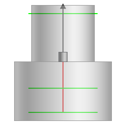
- Diameter One
-
Figure 1. 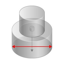
- Diameter Two
-
Figure 2. 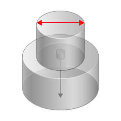
- Diameter Factor
- In some automated processes, the cylinder diameter is automatically set to the fastener shaft diameter. This leads to failed cylinder fasteners when the holes are properly modeled because the defined cylinder does not contain nodes. In such cases, the cylinder diameter factor has been introduced. This factor is set to 1.0 by default and is a multiplier for the cylinder diameter to increase the final cylinder diameter when necessary.
- Length One
-
Figure 3. 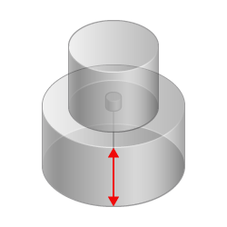
- Length Two
-
Figure 4. 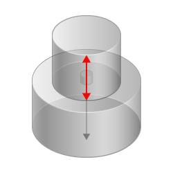
- Center Realization
- When enabled, the realization will be centered around the Connector
Position. When disabled, the realization will be centered around the found
Nodes. Figure 5 and Figure 6 demonstrate the
difference.
Figure 5. 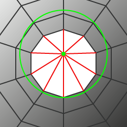
Figure 6. 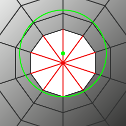
Element Details
- Create Head
- Allows the creation of an element per hole or prevents it. Figure 7 and Figure 8 demonstrate the difference
in the realization with these options.
Figure 7. 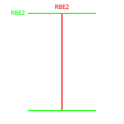
Figure 8. 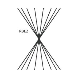
- Bolt Length
- The definition of the length of the body element.
Figure 9. 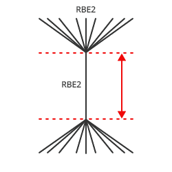
- Hole Gap
- Creates a body element with a length defined by the distance between the holes.
- Body Length
- Creates a body element with a specified length.
- Head Configs
- The element type to be used in creating the head of the realization.
- Head DOF
- The degrees of freedom (DOF) defined on the head element. This is only available for Rigid type elements.
- Number of Body Configs
- The number of elements between each hole layer.
- Body Configs
- The element type between each hole layer. If it is greater than 1, it can be
adjusted via a table. The Percentage Body Length allows the relative lengths
of each of the Elements within the body to be defined. Figure 10 shows one element with
Percentage Body Length set to the full length and another element with
Percentage Body Length set to zero connected at the end.
Figure 10. 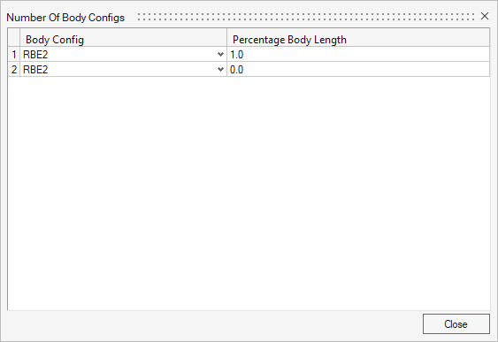
- Body DOF
- The degrees of freedom (DOF) defined on the body elements. This is only available for Rigid type elements.
- Number of Body Extensions
- The number of elements projected above the Shell element to half the thickness.
- Body Configs
- The element type in the body extension. If it is greater than 1, it can be adjusted via a table. The Percentage Body Length allows the relative lengths to be defined.
Connectivity
- Consider Hole
- Allows selected nodes to be limited to just those found on a hole or any of
the nodes found within the Cylinder.
Figure 11. 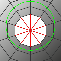
Figure 12. 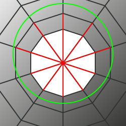
- Combine Links
- Allows all of the nodes found within each side of the virtual Cylinder to be
combined into a Single Rigid or a Rigid per link.
Figure 13. 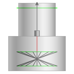
Figure 14.