Hole
The Hole realization is intended to generate a Mesh Dependent realization where you want to realize to the features within the mesh. It has the options to change the Mesh during the realization.
Realization Details
- Bar Diameter
- If there is a Property associated with the Control, these options will
be unavailable, as the property will define the Diameter values
independent from the realization.
- Auto
- Takes the minimum hole size to define the beam/bar cross section. The created Property will use this value as the beam cross section dimension.
- Input
- Can be used to define the Diameter of the beam cross section directly. The created Property will use this value as the beam cross section dimension.
- Detection and Feature Angle
- The minimum and maximum dimensions define which holes should be considered during fastener realization. The minimum and maximum feature angle define the features to be considered as hole edges for solid elements. The Feature angle is taken from the Meshing Preferences value.
- Pretensions
- An optional parameter that will create a pretension. The position of the
pretension will be per element/per layer at the centre of the element.
- Initial Stress
- The initial pretension stress value.
Element Details
- Create Head
- Allows the creation of an element per hole or prevents it. Figure 1 and Figure 2 demonstrate the difference
in the realization with these options.
Figure 1. 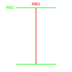
Figure 2. 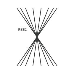
- Bolt Length
- The definition of the length of the body element.
Figure 3. 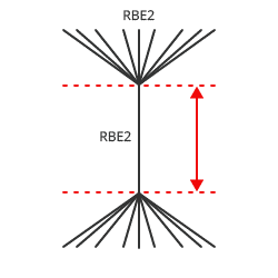
- Hole Gap
- Creates a body element with a length defined by the distance between the holes.
- Body Length
- Creates a body element with a specified length.
- Head Configs
- The element type to be used in creating the head of the realization.
- Head DOF
- The degrees of freedom (DOF) defined on the head element. This is only available for Rigid type elements.
- Number of Body Configs
- The number of elements between each hole layer.
- Body Configs
- The element type between each hole layer. If it is greater than 1, it can be
adjusted via a table. The Percentage Body Length allows the relative lengths
of each of the Elements within the body to be defined. Figure 4 shows one element with
Percentage Body Length set to the full length and another element with
Percentage Body Length set to zero connected at the end.
Figure 4. 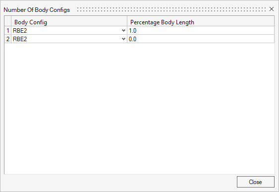
- Body DOF
- The degrees of freedom (DOF) defined on the body elements. This is only available for Rigid type elements.
- Number of Body Extensions
- The number of elements projected above the Shell element to half the thickness.
- Body Configs
- The element type in the body extension. If it is greater than 1, it can be adjusted via a table. The Percentage Body Length allows the relative lengths to be defined.
- Solid Hole
- Can be used to define the Connectivity within Solid Holes. There are
four different styles defined with the realization on the Solid Hole
being isolated.
Figure 5. Edge 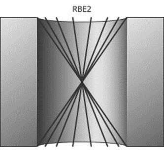
Figure 6. Interior 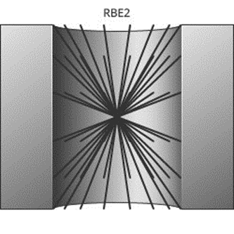
Figure 7. Layered Edge 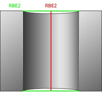
Figure 8. Layered Interior 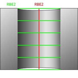
- Connect Outer Layer
-
- Single Layer
- Selects the realization to connect to the first layer of
elements from the edge of the hole.
Figure 9. 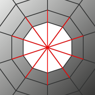
- Single Layer Alt
- Selects the realization to connect to the first layer of
elements skipping every second element from the edge of the
hole.
Figure 10. 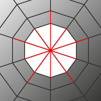
- Double Layer
- Selects the realization to connect to the first layer of elements from the edge of the hole with a secondary element.
- Double Layer Alt
- Selects the realization to connect to the first layer of elements skipping every second element from the edge of the hole with a secondary element.
- Node Location
- When creating a realization without a head, this option can be used to
define the location of the center of the realization. It is very common
for Explicit interfaces to have the center of the realization located on
the edge of the hole.
- Center
-
Figure 11. 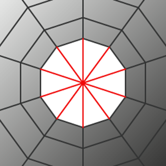
- Edge
-
Figure 12. 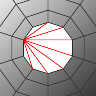
Connectivity
Hole Selection
- Existing Only
- A minimum of one hole per layer must be available. If holes do not
exist, the realization fails. This is the default method and must be
used for any type of solid meshes.
- Hole Mesh
- Can be used to change the hole mesh.
- None
- Leaves the hole mesh as is. Default for most operations.
- Fill
- Fill detected holes during fastener realization. There are various quad patterns available, which cause a remeshing of the area around the hole.
- Density
- Adjust the number of nodes around the hole.
- Number of nodes
- Specify the exact number of nodes (default is eight). The surrounding mesh gets remeshed.
- Element Size
- Specify an element size (default is 5.0). The number of elements around the hole is calculated based on this size. This is the preferred option for extremely different hole diameters. The surrounding mesh gets remeshed.
- Auto
- Perform a node distribution based on the underlying mesh size. The number of nodes is always rounded to an equal number.
- Washer Layer
- For 2D holes, one or two washer layers can be created, after which the surrounding mesh gets remeshed.
- Create Missing
-
- Hole Mesh
- Can be used to change the hole mesh.
- None
- Leaves the hole mesh as is. Default for most operations.
- Fill
- Fill detected holes during fastener realization. There are various quad patterns available, which cause a remeshing of the area around the hole.
- Density
- Adjust the number of nodes around the hole.
- Number of nodes
- Specify the exact number of nodes (default is eight). The surrounding mesh gets remeshed.
- Element Size
- Specify an element size (default is 5.0). The number of elements around the hole is calculated based on this size. This is the preferred option for extremely different hole diameters. The surrounding mesh gets remeshed.
- Auto
- Perform a node distribution based on the underlying mesh size. The number of nodes is always rounded to an equal number.
- Hole Search
- Not all the holes found in the given connector tolerance can be considered for the various fastener realizations.
- Set Hole Diameter
-
- New
- Create new holes with the specified diameter.
- All
- Create new holes with the specified diameter and adjust existing holes with the specified diameter.
- Washer Layer
- For 2D holes, one or two washer layers can be created, after which the surrounding mesh gets remeshed.
- Align Hole
- Moves the center of a hole into the position of the projection point.
- Unrealize Fill Hole Created
- The created holes during the realization are filled when the connector is unrealized, returning the surface back to its original configuration before realization.
- Use Available
- Creates hybrids (hole on one side only), but other combinations are
allowed. On the mesh side (no hole), the connection is realized via the
head elements defined in the chosen realization type. The head
element(s) is/are created between the appropriate body element node and
the nodes inside the diameter (no hole connection diameter) defined
under the Realization Details heading. This option is used for
realization types which are not eager for holes.
- Hole Mesh
- Can be used to change the hole mesh.
- None
- Leaves the hole mesh as is. Default for most operations.
- Fill
- Fill detected holes during fastener realization. There are various quad patterns available, which cause a remeshing of the area around the hole.
- Density
- Adjust the number of nodes around the hole.
- Number of nodes
- Specify the exact number of nodes (default is eight). The surrounding mesh gets remeshed.
- Element Size
- Specify an element size (default is 5.0). The number of elements around the hole is calculated based on this size. This is the preferred option for extremely different hole diameters. The surrounding mesh gets remeshed.
- Auto
- Perform a node distribution based on the underlying mesh size. The number of nodes is always rounded to an equal number.
- Hole Search
- Not all the holes found in the given connector tolerance can be considered for the various fastener realizations.
- Set Hole Diameter
- All holes in the realization will be adjusted to the specified diameter.
- Selection Diameter
- Connect a link without an available hole by joining the nodes found inside the circle with the specified diameter around the projection point via head elements. Used if holes are not required when using the use hole if available option or fill and remesh hole if available option.
- Align Hole
- Moves the center of a hole into the position of the projection point.
- Remove
- Use this option when you do not want the shape of holes to interfere
with the mesh flow in the fastener region. The detected holes are closed
and a remesh of the new elements and a few additional rows of adjacent
elements is performed. The connection is realized via the head elements
defined in the chosen realization type. The head elements are created
between the appropriate body element nodes and the nodes inside the
diameter (no hole connection diameter) defined under the Realization
Details heading.
- Hole Search
- Not all the holes found in the given connector tolerance can be considered for the various fastener realizations.
- Selection Diameter
- Connect a link without an available hole by joining the nodes found inside the circle with the specified diameter around the projection point via head elements. Used if holes are not required when using the use hole if available option or fill and remesh hole if available option.