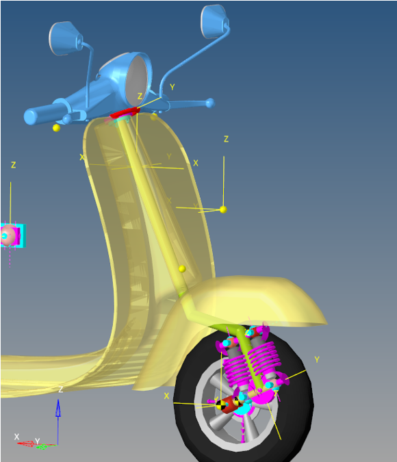
As the name suggests, the trailing arm is pivoted to the steering column at one side.
Spring and dampers are mounted between the trailing arm and the steering column with a fore
and aft arrangement. The wheel is mounted at the rear end of the trailing arm.
Figure 1. Single Side Trailing Link Suspension with Steering
Model Use
The Single Side Trailing Link Suspension system can be used in front half vehicle or full
vehicle models of a two wheeler. The default geometry and mass approximate that of a two
wheeler scooter, but the model and data can be revised to reflect any size two wheeler.
Note:
The wheel body represents the mass and inertia of the tire and
the rim.
The wheel hub body represents the mass and inertia of other rotating bodies such as
a brake rotor. The wheel hub and brake rotor have no associated graphics.
The wheel and wheel hub parts use the Wheel center location as the center of
gravity.
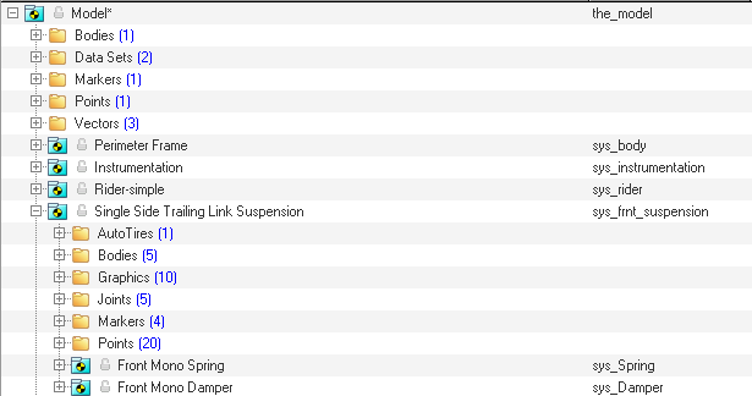
The image below shows the Model Browser view of the systems on a fully
populated front suspension model. The Single Side Trailing Link Suspension system has two
“child” systems.
Figure 2. Browser View of Single Side Trailing Link Suspension
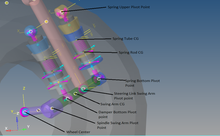
Points
Points locate the joints and bushings that connect the
suspension bodies to one another. The image below shows the principal points for
the Single Side Trailing Link Suspension.Figure 3. Right Side Principal Points – Single Side Trailing Link Suspension
Note: Suspension is located on the right side of the front wheel.
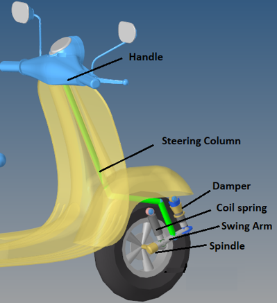
Bodies
The Single Side Trailing Link Suspension is comprised of the bodies shown in the image
below: Figure 4. Right Side Bodies – Single Side Trailing Link Suspension
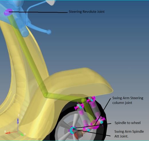
Joints
The table below describes the joints for a Single Side Trailing Link Suspension:
Label
Type
Body 1
Body 2
Point
Notes
Steering Swingarm Attachment Joint
Revolute
Swing Arm
Steering Column
Swingarm steering Att Point
Swingarm Spindle Att Joint
Fixed
Spindle
Swing Arm
Front Wheel CG
Spindle to Wheel
Revolute
Front Wheel
Spindle
Front Wheel CG
Steering REV Joint
Revolute
Handle
Frame
Steering Axis Top
Handle
Fixed
Handle
Steering Column
Steering Axis Top
The following image shows the location of the joints in the suspension:Figure 5. Joints - Single Side Trailing Link Suspension