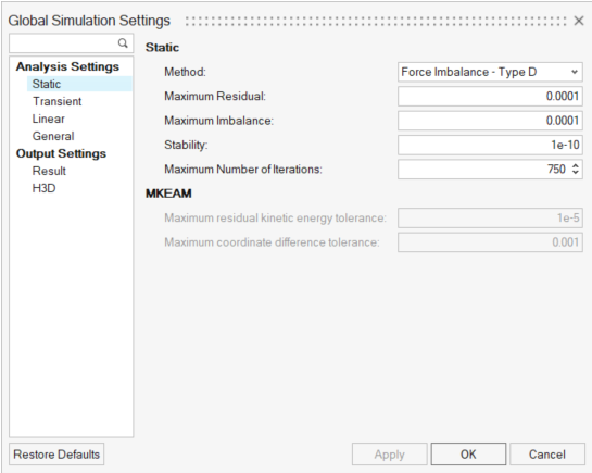
The Global Simulation Settings dialog offers access to global simulation parameters and
output options for the run. The parameter values are applicable for all the Analyses in the
model unless they are overridden by their corresponding parameters in the Analysis through its
Entity Editor.
From the Run Motion Analysis dialog, click Global simulation
settings to display the following dialog:Figure 1. Global Simulation Settings Dialog
Analysis Settings
Analysis Settings are used to control the solver parameters during the
simulation.
Static
Set the Static solver method options.
Option
Description
Method
Select the type of Static
solver method from the drop down:
Force Imbalance Method that uses a time integration approach
for quasi-static simulation. Not applicable for Static
simulation (MotionSolve defaults to
Force Imbalance – Type S) for pure static simulation. While
using this method, the solver also uses the Transient simulation
settings.
Max Kinetic Energy Attrition
Uses the Maximum Kinetic Energy Attrition Method based on
conservation of energy. This method is suitable for models with
contacts. This method does not work for quasi-static
simulation.
The following options are
available if Force Imbalance - Type D/Type
S is chosen:
Maximum Residual
This specifies the upper limit for the change in residual of
the system equations at the static equilibrium point.
Maximum Imbalance
Specifies the maximum force imbalance in the equations of
motion that is allowed at the solution point.
Maximum Number of Iterations
Specifies the maximum number of iterations that are allowed
before simulation stops.
Stability
Specifies the fraction of the mass matrix that is to be added
to the Jacobian to ensure that it is not singular.
The following options are
available if MKEAM is chosen:
Maximum number of iterations
Specifies the maximum number of iterations that are allowed
before simulation stops.
Maximum residual kinetic energy
tolerance
Specifies the maximum allowable residual kinetic energy of
the system at the static equilibrium point.
Maximum coordinate difference
tolerance
This specifies the upper limit for the change in system
states at the static equilibrium point.
Transient
Set the integrator options.
Option
Description
Integrator Type
Select the type integrator from
the drop down:
ABAM
VSTIFF
MSTIFF
DSTIFF
The following common options
are available for all integrators:
Maximum Step Size
Defines the maximum step size the integrator is allowed to
take.
Integrator Tolerance
Represents the maximum absolute error per step that the
integrator is allowed in computing the displacement, velocity,
and differential equations states.
Constraint Tolerance
Defines the accuracy to which the system configuration and
motion constraints are to be satisfied at each step.
Maximum Order
Specifies the maximum order that the integrator is to
take.
Maximum Initial Step Size
The maximum initial step size.
Minimum Step Size
Defines the minimum step size the integrator is allowed to
take.
Velocity Tolerance Fact
The factor that multiplies integr_tol to yield the error
tolerance for velocity states. For the DSTIFF integrator, this
option is only applicable when the DAE
Index is set to 1 and the Velocity
Control option is selected.
The following options are
specific to DSTIFF:
DAE Constraint Tolerance
The tolerance on all algebraic constraint equations that the
corrector must satisfy at convergence.
DAE Index
The index of the DAE formulation. Options available are:
3 or
1.
DAE Corrector Maximum
Iteration
The maximum number of iterations that the corrector is
allowed to take to achieve convergence.
Initial Number of Jacobian Matrix
Evaluation
This attribute controls the Jacobian matrix evaluation during
corrector iterations. Options available are: Auto|1|2|3.
Auto
The solver automatically determines when a new
Jacobian needs to be calculated.
Value n (1, 2, or 3)
Indicates the nth iteration at which a
new Jacobian is calculated.
Velocity Control
The logical flag that controls whether the velocity states
are checked for local integration error at each step. This
option is only available in the case where the DAE index =
1.
DAE Interpolation
Specify whether the integrator should interpolate results at
the output steps. When turned on, MotionSolve is forced to interpolate the
results at output steps while simulating from start time to end
time.
Linear
Set the linearization options.
Option
Description
Eigen Values And Vectors
Specifies whether the eigenvalue and eigenvector data is
written to a .eig file.
Disable Damping
Specifies whether the linearization solver should disable
damping from all force elements for the eigenvalue
solution.
Kinetic Energy Distribution
Specifies whether the modal kinetic energy distribution is
written out to the solver log file and the
*_linz.mrf output file.
Generate State Space Matrix
AltairCompose/Twin Activate OML
Specifies whether the A, B, C and D matrices are to
be written out into a .oml file
that can be read in by Compose/Twin Activate.
MATLAB
Specifies whether the A, B, C and D matrices are to
be written out into a file that can be read in by
MATLAB.
Simulink MDL
Specifies whether the A, B, C and D matrices are to
be written out in Simulink MDL format or not.
Animation Scale
The animation scale. Used for linear analysis to set the
scale factor for the modal animation. Default = 1.
General
Set the general options.
Option
Description
Number of CPU cores in SMP run
Specifies the number of CPU cores to be used when multiple
cores are available. This is particularly helpful in
parallelizing computations in the case of Contact
simulation.
Mesh coarseness for contacts
Default coarseness setting for meshing CADGraphics when in
contact. MotionView will use this
setting while generating a mesh during solver export for those
CADGraphics on which mesh coarseness has not been individually
set.
Default location for solver run
files
The default location for solving. When not specified, the
solver deck is written at the model location.
Write Msolve Python file
Writes a MotionSolve Python file
for live run. This python file can be used for
debugging.
Export MDL animation file
Write an .maf file which can be loaded
as a model in HyperView to view
results with .mrf.
Output Settings
Output Settings are used to set user preferences on output options.
Result
Set output file types, zero
tolerances, and debug options.
Option
Description
Plot file options
Multibody Result File (MRF)
Writes result files in the .mrf
format.
ASCII Plot File (PLT)
Writes plot files in the .plt
format.
Altair Binary File (ABF)
Writes plot files in the .abf
format.
Do Not Append REQ/id To Output
Turn ON this setting to avoid a prefix
being added to the names of the output (a three letter keyword,
followed by the output ID - for example,
REQ/70000001).
Capture Max Penetration During
Contact
Flags the solver to introduce extra output between two time steps
when the penetration depth is larger than both of the time
steps.
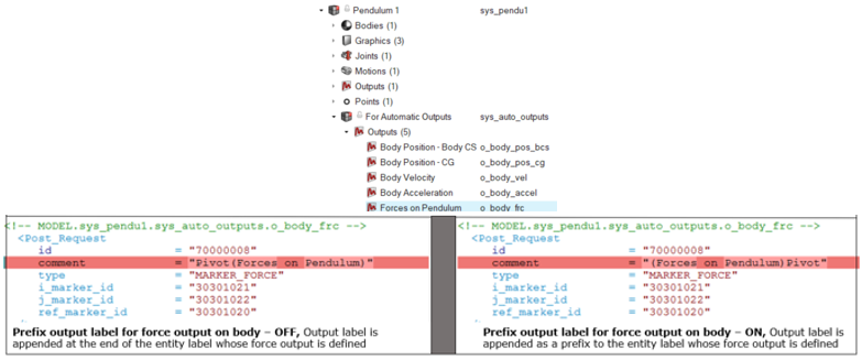
Prefix Output Label For Force Output On
Body
Controls how the label from a Force type Output on any body is
written to the solver deck.
Note: With Prefix output label for
force output on body option on, the output label
is added as a prefix to the label of the connection to the body.
Otherwise, the output label is appended at the end of the label
of the connection.
Write Result Data Per Time
Select the result data per time output in the ABF and PLT files
when there is more than one result available at a given time.
Options available are: ALL,
FIRST, or
LAST.
Measure Rotation
Select the format for angular results from the drop-down menu.
Options available are: YAW_PITCH_ROLL or
EULER_ANGLES.
Zero Tolerance
Displacement
Output displacements less than the specified value are set to be
equal to zero.
Velocity
Output velocities less than the specified value are set to be
equal to zero.
Acceleration
Output accelerations less than the specified value are set to be
equal to zero.
Force
Output forces less than the specified value are set to be equal
to zero.
Debug Options
Write Debug Info
A logical flag that controls the generation of debugging
information about the solver analysis steps.
Generate Animation At Each Iteration (Static
Simulation Only)
A logical flag that controls the generation of animation frames
at each iteration for debug purposes.
H3D
Set animation file preferences.
Option
Description
Animation File (H3D)
Writes animation file in .h3d
format.
Contact Forces
Contact force vector animation in the
.h3d file.
Flexible Bodies Velocity and
Acceleration
Velocity and acceleration output for flexible bodies during a
MotionSolve run.
Format
Select the H3D file format from the drop-down:
Modal
Nodal
Auto
Stress
Select the stress format in H3D file from the drop-down:
None
Tensor
Direct
Strain
Select the strain format in H3D file from the drop-down:
None
Tensor
Write H3D Results for Every
Step
Controls the frequency of writing results into an
.h3d file.
Write H3D Results Starting At
Controls the start time of writing results into an
.h3d file.
Stop Writing H3D Results At
Controls the end time of writing results into an
.h3d file.