FEMFAT spotwelds are a particular realization type that conforms to the
specifications outlined in the FEMFAT fatigue software.
Naming Conventions
This connector fits within the FEMFAT scheme to enable you to create a FEMFAT
compatible spotweld within HyperMesh. Materials,
properties, sets and systems are created with the appropriate names so it can be
recognised when the model is read in FEMFAT.
MAT151 (ELSET which contains elements which has
MAT151)
MAT152 (ELSET which contains elements which has
MAT152)
C115 (NSET contains nodes assigned to coordinate system
115)
C120 (NSET contains nodes assigned to coordinate system
120)
C350 (NSET contains nodes assigned to coordinate system
350)
System Collector
C_(System ID)
C_(System ID)
C_(System ID)
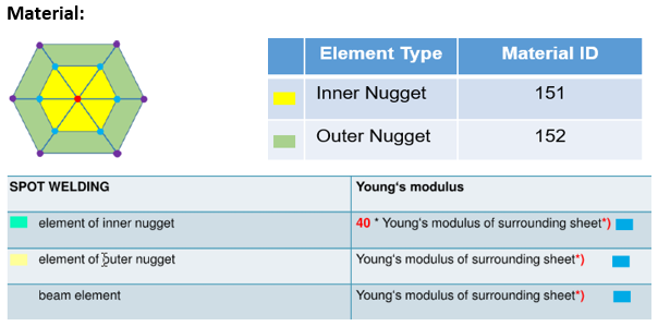
Material
Materials adhere to the following rules:
The material ID created for inner and outer nuggets should be based on the
interpretation of the base material.
Note: If base material E > 150,000
N/mm2, then the material is considered as steel. In this case, follow
these rules:
Inner Nugget Material ID should be 151
Outer Nugget Material ID should be 152
Note: If base material E < 150,000 N/mm2, then the
material is considered as aluminum. In this case, follow these rules:
Inner Nugget Material ID should be 154
Outer Nugget Material ID should be 155
Inner Nugget should have mat ID = 151/154. Young's modulus of Mat 151/154 is
calculated as 40 * Base sheets young's modulus.
Outer Nugget should have mat ID = 152/155. Young's modulus of Mat 152/155 is
equal to the surrounding sheet.
Beam element is assigned Mat ID =152.
If Young’s modulus is different for links, then the average Young’s modulus
is used.
If mat ID already exists in the session, it will be reused.
Figure 1.
Property
Table 3. Shell Property
Profile
Description
Nastran and OptiStruct
PSHELL property with thickness derived from parent
property.
Abaqus
SHELLSECTION property with thickness derived from
parent.
Table 4. Bar Property
Profile
Description
Nastran and OptiStruct
PBAR property is created and assigned a beam section
(standard Rod section). The diameter of the rod should be the
same as that of the FEMFAT weld diameter.
Abaqus
BEAMGENSECTION property is created and a generic beam section
is assigned.
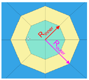
Diameter
Router = Input Diameter
Rinner = 0.58 * Input DiameterFigure 2.
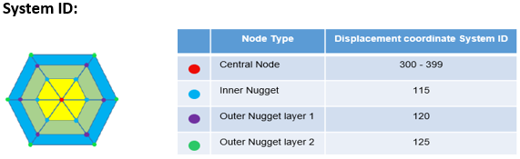
System ID
The System ID adheres to the following rules:
If total dia < 2.5, the System ID = 300. If total dia > 9.9, the System
ID = 300.
If diameter is in range 2.5-9.99, then create system between 325-399.
Simple approach would be 300 + (Dia *10).
If Dia = 2.5, the System ID = 325. If Dia = 9.9, the System ID = 399.