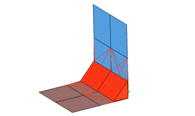
Creates penta elements with RBE3 elements projecting and connecting to the surrounding
shell elements. This realization supports many different use cases, including T-joint,
angled T-joint, lap joint and butt joint.Figure 1.
Penta Realization Options
Figure 2.
Option
Action
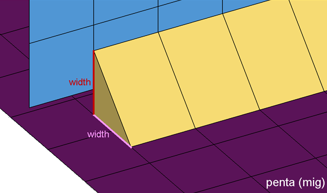
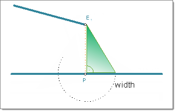
width
Specify the length of a penta.
Note: Only available for penta
(mig), penta (mig + L), penta (mig + T), and penta (mig +
B).
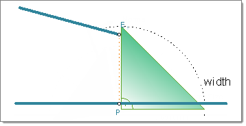
fitted/equilateral/equilateral-fitted
Select the size and shape
of a penta.
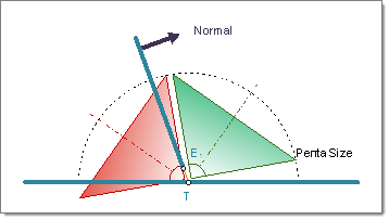
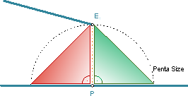
fitted
The length of one penta edge is the exact projection distance, and the
length of the other penta edge is defined by the width value; the penta
has an right-angle.Figure 3. Example: Fitted
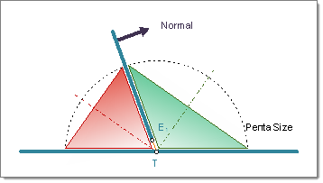
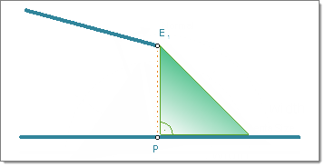
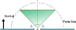
equilateral
Create an equilateral penta; leg lengths are defined by the width
value.Figure 4. Example: Equilateral
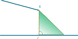
equilateral/fitted
Combination of fitted and equilateral; you do not need to define a width
when you select this option.Figure 5. Example: Equilateral/Fitted
Note: Only available for penta (mig) and penta (mig + L).
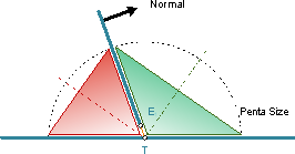
right-angled
Create a right-angled penta that is oriented around the
bisector. Clear this checkbox to create an angle adapted penta.Figure 6. Right-Angled T-weld Penta Created on Both Sides of the Normal Figure 7. Angle Adapted T-weld Penta Created on Both Sides of the Normal
Note: Only available for penta (mig) and penta (mig + T).
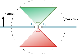
both sides/positive sides/negative sides
Select which side of the normal to create
the penta on.
(mig + L)
The negative side is the side where the links are fairly parallel to
each other. The angle that is close to 90° (88° to 90°) the element
normal of the first found shell element at the free edge decides which
side is the positive and the negative side.
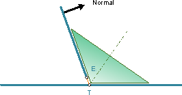
Figure 8. Example: (mig + L)
(mig + T)
The positive side is normally the side with the obtuse angle. The angle
that is close to 90° (88° to 92°) the element normal of the first found
shell element at the free edge decides which side is the positive and
negative side.
Figure 9. Example: (mig + T)
(mig + B)
The positive side is the side where the element normal of the first link
points to.
Figure 10. Example: (mig + B)
Note: Only available for penta (mig), penta (mig + L), penta
(mig + T), and penta (mig + B).
edge details
In many cases, the connector position is not very
precise. To create the requested result, an automatic edge snapping can be enabled.
In the first step the connector snaps to, for example, the closest free edge, and
then from there the projection and FE creation starts. Select how many element rows
away from the free edge to snap the connector to for L and T connections.