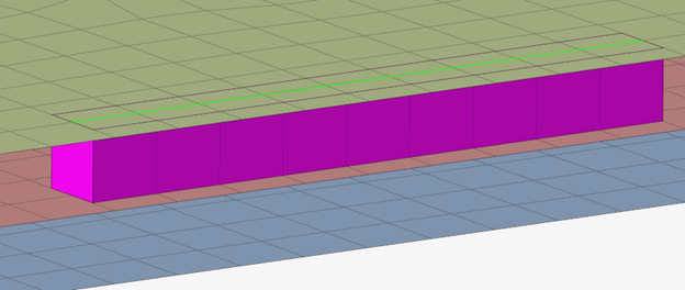
This realization creates hexa elements between shell and/or solid elements in order
to connect them using a contact definition.
The hexa element nodes will project and touch the shell and/or solid element faces.
During the realization, a contact and referencing main and secondary sets are
created; unless defined differently, the hexas are assigned a default property and
material, and are organized into a component with the same name base as the
property.Figure 1. Hexa (Contact) Realization Example
Legacy Realizations
The following realizations are replaced by Hexa (Contact):
hexa (seam tie)
hexa (adhesive – contact)
Hexa Realization Options
Exclusive options available for seam realization types with hexa row(s) representing
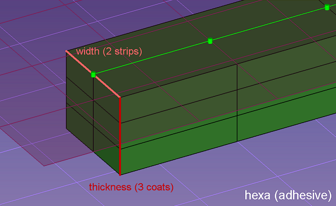
the connection.Figure 2.
Option
Action
width
Define the width of the continuous hexa weld in the direction
perpendicular to the seam direction.
Note: Only available for
hexa (adhesive) and hexa (RBE2-RBE3).
strips
Define the number of hexa elements required along the
width.
coats
Defines the number of hexa elements required along the
thickness.
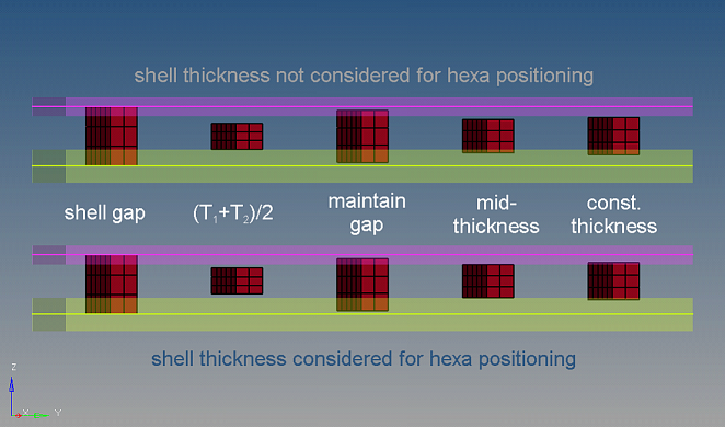
thickness
Select a method for defining the thickness of a hexa
weld.
shell gap
Project the hexa to touch the shell elements.
The position is independent from any thickness.
(T1+T2)/2
Hexa size (thickness) depends on the shell thickness of the connected
parts.
mid thickness
Calculate the hexa size (thickness) as the air gap between the two
connected parts.
If there is no gap, or even a penetration, the hexa size is always
modeled with 1.0.
const. thickness
Specify the hexa size (thickness).
maintain gaps
Calculate the hexa size (thickness) as the gap distance reduced by two
times the specified value for maintain gaps.
The position is independent from any thickness.
Note:
The exact hexa position is also influenced by the
consider shell thickness and offset for solid
positioning option.
Only available for hexa (adhesive) and hexa
(RBE2-RBE3).
Figure 3.
thickness dependent / angle, D and H / H1, H2 and D
Select a method to define how hexas are positioned and
located, and assign appropriate values to any corresponding inputs.
thickness dependent
tmin
min(t1;t2)
d
factor_a * tmin
h1
factor_b + 2.5 * t2
h2
factor_b + 2.5 * 211
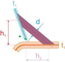
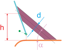
Figure 4.
angle, D and H
angle α
angle to the base sheet
d
thickness of hexa
h
height from the basesheet
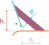
Figure 5.
H1, H2 and D
h1
distance on T sheet
h2
distance on basesheet
d
thickness of hexa
Figure 6.
discontinuity
By default, the length and pattern of a hexa weld is defined
by test points along the seam connector. To ignore the
predefined test points, and define a specific element length,
weld length, and break length to realize the connector with,
select the discontinuity checkbox. With this option, a hexa
adhesive seam with alternating weld pieces and gaps is created.
When discontinuity is enabled, you must define the
following inputs:
elem length
Specify the length of a hexa along the seam
connector.
weld length/scale (elem)
Specify the length of the hexa weld.
break length/scale (elem)
Specify the amount of space to place in between
the hexa welds.
If the defined lengths do not fit exactly to the seam
connector length, mathematical correct rounding is used. To
guarantee, that the rounded lengths are not too far away
from the expected values, minimum and maximum deviations are
defined in the seam options.
Note: Only available for
hexa (adhesive) realizations.
hexa position to edge
Select a location to create the hexa from the edge.
midpoint
Position the hexa to the exact location of the
connector after snapping.
offset from edge
Specify a distance from the edge to offset the
hexa.
positive edge
Position the hexa to the outside of the edge.
The positive side is normally the side with the
larger angle.
negative edge
Position the hexa to the inside of the edge.
The negative side is normally the side with the
smaller angle.
The angle that is close to 90° (88° to 90°) the element
normal of the first found shell element at the free edge decides
which side is the positive and the negative side.
Note: Only
available for hexa (adhesive) and hexa
(RBE2-RBE3).
edge details
In many cases, the connector position is not very
precise. To create the requested result, an automatic edge snapping can be enabled.
In the first step the connector snaps to, for example, the closest free edge, and
then from there the projection and FE creation starts. Select how many element rows
away from the free edge to snap the connector to for L and T connections.