Restriction: Available in LS-DYNA, Nastran, OptiStruct, Radioss, and PAM-CRASH.
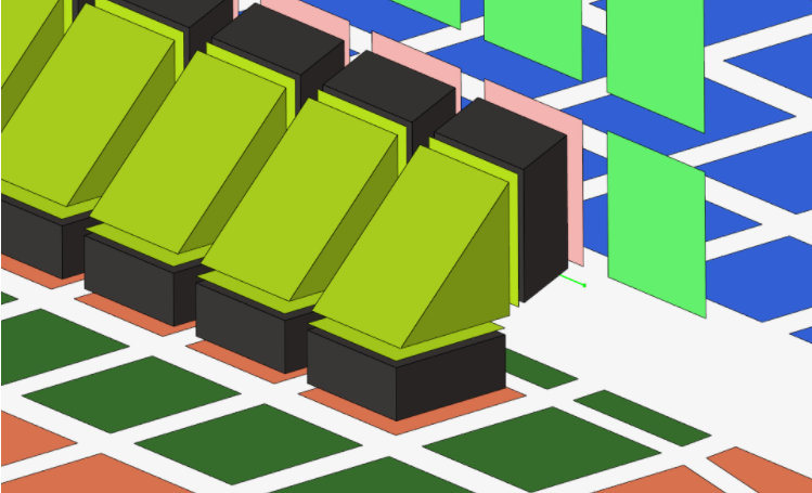
Use the penta imprint realization to create seam lines between T joint
shell parts.
Contacts are defined between the shell components and the appropriate hexa nodes. A heat
affected zone for the shells from ultra-high strength steel material is also created.
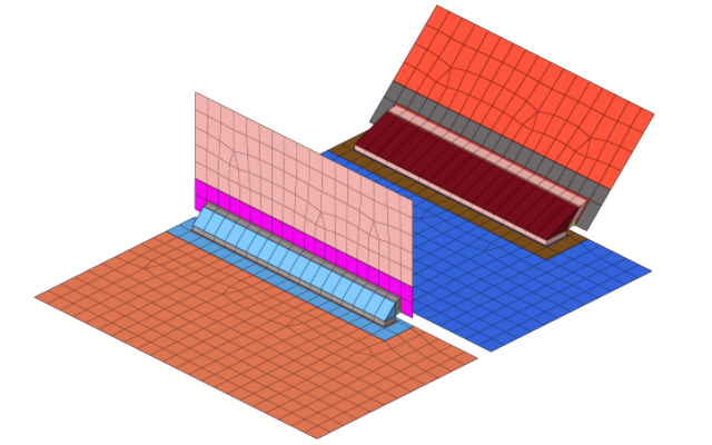
Define the heat affected zone dimensions using the parameters available in the
Connector Entity Editor. The dimension and property of each
heat affected zone (HAZ) can be separately defined.Figure 1.
Hexa element connected to a shell element which transmits to the core penta element.Figure 2.
General Info
Table 1.
Parameter
Action
Tolerance
Specify a distance from the connector location. Only the
entities within this tolerance can be taken into account for the
final realization. The tolerance is used to verify whether
adequate link candidates are available to be connected with
respect to the number of layers.
Connectivity Info
Table 2.
Parameter
Option
Connectivity
Note: By default, Connectivity is set to
contact, but you can also choose imprint.
HAZ
Create the quad weld elements and stitch them to both links
by adjusting their mesh. Perform all required HAZ.
Enable Condition HAZ
Control which parts need to receive heat affected zones
during the realization.
Skip Imprint
Create the quad weld elements, but do not change the meshes
of the links.
Instead, create additional elements to represent
the requested HAZ. These elements are organized in the
^conn_imprint component.
You can use these elements
for a later manual imprint after they have been manipulated
to your need. This can be helpful in more complex areas,
where the standard imprint functionality fails, for example,
when working with conflicting connectors.
Note: The quad weld elements are not
attached to the links. The connection needs further
attention.
Contact Info
Table 3.
Parameter
Action
Contact Creation Option
Choose a method for creating contacts.
one contact per link
Create one exclusive contact with two exclusive sets
per each link.
Create the contact between the link and the hexa
nugget nodes laying on this link. The nodes of one
hexa nugget belong to two different contact
definitions.
Enable the selection of UHSS material which controls which
parts need to receive heat affected zones during the
realization.
UHSS Material Option
Choose a method for selecting UHSS material.
From current model
Select an existing material from current model.
In the Connector Entity Editor, the UHSS Material
Entity ID’s field is populated with the number of
the materials selected.
From search file (default)
Select material from a search file.
For Hexa Nugget Connector realizations the material
search file name is
materialsnippets.txt.
HyperMesh searches for
this file in the following locations and in the
following order:
Current working folder:
[CURRENTWORKINGDIR]/materialsnippets.txt
In the Connector Entity Editor, the UHSS Material File field is populated with
the name of the file that was found last.
The text file contains snippets from the material
names, which need to receive heat affected zones
during the realization.
From connector metadata
Once a connector is realized with the UHSS Material
Option “From search file”, the folder name is
written as metadata to the connector in a relative
manner to allow the exact same rerealization in a
different work environment as long as the same
materialsnippets.txt files
are saved in according folders.
HAZ Dimension Scheme
Choose a setting for defining HAZ diameters.
HAZ Inner Diameter
values
Specify an absolute value for the HAZ Inner
Diameter.
Note: This value
must be greater than the value used for defining
the nugget diameter.
scale factors
Calculated as a scale factor from the nugget
diameter.
Note: This value
must be greater than or equal to 1.0.
offsets
Specify a HAZ Inner Diameter which is offset from
the nugget diameter.
HAZ Outer Diameter
values
Specify an absolute value for the width of the first
layer around the HAZ Inner Diameter.
scale factors
Specify a width for the first layer around the HAZ
Inner Diameter. Calculated as a scale factor from
the nugget diameter.
offsets
Specify a width for the first layer around the HAZ
Inner Diameter which is offset from the HAZ Inner
Diameter.
Note: For values
and scale factors, this value must be greater than
the value used for defining the HAZ Inner
Diameter.
HAZ Layer 2
Enables you to specify the HAZ Outer Diameter 2. By default,
this checkbox is cleared and the HAZ Outer Diameter 2 cannot be
defined.
HAZ Outer Diameter 2
values
Specify an absolute value for the width of the
second layer around the HAZ Outer Diameter.
scale factors
Specify a width for the second layer around the HAZ
Outer Diameter. Calculated as a scale factor from
the nugget diameter.
offsets
Specify a width of the second layer around the HAZ
Outer Diameter, which is offset from the HAZ Outer
Diameter.
Note: For values and scale factors, this
value must be greater than the value used for defining the
HAZ Outer Diameter.
Property and Material Info
Use the Property and Material Info parameters to define the properties and materials
of the welds and the heat affected zones (HAZ).
Table 5.
Parameter
Option
HAZ Material Option
Choose a method for assigning material for the HAZ.
Use original material
Assign a new HAZ component with the same material
that was assigned to the original components.
Use copy of original material
Duplicate the original materials and assign them to
new components.
The original material is duplicated.
The new material name will be the same as the
original material with _HAZ_mat as a postfix.
Select a material
Select a material from the current model via the
select material for HAZ option. HAZ components are
created with the same name as the selected material
with property ID as a postfix.
When set to <unspecified>, a default material is
taken from the
[hm_scripts_dir]/connectors/hexa_nugget/dyna/hexa_nugget_HAZ_material_default.ini
file. HAZ components are created with name
hexa_nugget_HAZ_mat_default_ and with the property
ID as a postfix.
HAZ Property Option
Choose a method for assigning a property to HAZ.
Use original property
Assign a new HAZ component with the same property
that was assigned to the original components.
Use copy of original material
Duplicate the original properties and assign them to
new components.
The original property is duplicated.
The new property name will be the same as the
original property with
_HAZ_prop as a postfix.
Scale original thickness
Create a new property and component for each link
that has a HAZ imprinted.
The property is a copy of the original. Properties
are named as
<originalname>_<HAZ_prop>_<scaled
thickness>, and components are named as
<matname>_<scaled property
name>.
Input thickness
Create a new property and component for each link
that has a HAZ imprinted.
The property is a copy of the original. Property is
named as
<hexa_nugget_HAZ_prop>_<thickness_value>,
and components are named as
<matname>_<Input thichness prop
name>.
Select a property
Select a property from the current model via the
select property for HAZ option.
HAZ components are created and named using the UHSS
material with the property ID as a postfix. For
example, <UHSS matname>_<prop
ID>.
Nugget Material Option
Choose a method for creating and assigning material to nuggets.
Create one material per each link combination
Create one material for each link combination.
The weld material is named
<hexa_nugget_weld_mat>_<link 1
ID/name>_<Link 2 ID/name>.
If the link with ID 1 and the link with ID 2 are
connected, than the weld material which gets created
will be named
hexa_nugget_weld_mat_1_2.
Create one material per each number of layer
Create one material based on the number of layers
the weld is connecting to.
The weld material is named
<hexa_nugget_weld_mat>_<link 1 ID/
name>_<No. of layers>.
If it is a 2T weld, than the mat name will be
hexa_nugget_weld_mat_2L.
If it is a 3T weld, than it will be named
hexa_nugget_weld_mat_3L.
Use one single weld material
Select a weld material from the current model using
Select Nugget Material Option. The selected material
will be assigned to all weld elements.
Itemize Multilayer Connections
Itemize a multilayer connection. For example, in the case of
a three layer connection, the two hexa clusters will be handled
separately and will be assigned two different materials. At the
same time, a two layer connection between the same two links
will be assigned another material.
Names are created as following:
hexa_nugget_weld_material_link1_link2_(link3)
Ideally the links are ordered as
<outer involved link>_<inner
involved link>_(<uninvolved comp>),
so that the two links involved come first, and the
link(s) that are not involved are written in
brackets.
hexa_nugget_weld_material_link3_link2_(link1)
Ideally the links are ordered as
<outer involved link>_<inner
involved link>_(<uninvolved comp>),
so that the two links involved come first, and the
link(s) not involved are written in brackets.