Promotes design exploration of early concepts and mature structures.
The Exoskeleton tool provides insight as to how the structure may need reinforcing to
meet a predetermined performance criteria.
The following optimization types are available:
Topology
Provides high-level design direction to determine where the structure
can benefit from reinforcing.
Size
If the location is known or the design space location is defined
already, use Size optimization to provide design
direction more accurately, as it provides accurate diameter and wall
thickness as a result.
From the Design Space ribbon, select the Exoskeleton
tool.
Figure 1.
From the guide bar, select
Components or Elements to
select them from the model.
1D, 2D, and 3D components and elements are supported.
Note: Geometry is not supported as a valid
input.
Optional: From the guide bar, select
Hardpoints to select one or more hardpoints.
If there is a specific location where the exoskeleton must pass through and be
connected, then selecting one or more hardpoints ensures you create the
appropriate lattice structure.
Optional: From the guide bar, select
Material to assign an existing material to the
exoskeleton.
Selecting a material is optional and can be generated and assigned as a
separate post step.
Optional: From the guide bar, select
Symmetryto create an exoskeleton 1D lattice structure
in symmetry.
You can define the lattice in symmetry using OptiStruct to ensure a truly symmetric optimization
output.
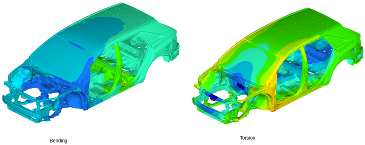
Topology and size optimization examples are illustrated below. The loading conditions
consider two simple bending and torsion load cases:Figure 2.
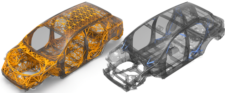
Topology Optimization
In the figure below, the image on the left illustrates the newly
generated exoskeleton (see orange 1D elements). These 1D elements define
the exoskeleton lattice design space. The exoskeleton has tied contact
defined between the nodal junctions of the exoskeleton (secondary set)
and the original structure (main set). One single DTPL design variable
is automatically created.
Once the problem is defined, submit the optimization. The output in this
case, for topology, removes unwanted design space material that is not
required. The image on the right shows the output from the topology
optimization for the bending and torsion case. For the torsion load
case, it is reinforced near the front shock towers; for the bending load
case, it reinforces the structure around the rear door opening.
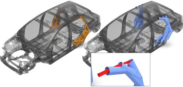
Figure 3.
Size Optimization
In this example, the location of the design space is known (see the
orange 1Ds), however the reinforcement composition details are unknown.
The figure on the right (the blue elements) is the result of the size
optimization. All beam elements that have little or no influence are
manually deleted. The remaining elements provide the necessary design
guidance. In this case, it retains the 1Ds that give the largest
footprint in that localized area and maximizes the diameter while
minimizing the wall thickness (to reduce mass). Results vary depending
on the optimization problem definition.