2D Meshing
In this tutorial, you will create, adjust, and edit mesh.
Before you begin, copy the file(s) used in this tutorial to your
working directory.
In this tutorial you will:
- Create an initial mesh
- Adjust the mesh
- Edit the mesh
Create Mesh
In this step, you will create and inspect the initial mesh.
- Start HyperMesh.
- From the menu bar, click .
-
Browse to your working directory, select
BracketLeg_Start.hm, and click
Open.
The model opens in the modeling window.
-
From the Topology ribbon, select the Edit
Parameters tool.
Figure 1. 
-
In the Parameter Editor dialog, click
 and browse and open the
crash_2mm.param file.
and browse and open the
crash_2mm.param file.
- Click Apply and close the Parameter Editor dialog.
-
From the Topology ribbon, select the Edit
Criteria tool.
Figure 2. 
-
In the Criteria Editor dialog, click and browse and open the
crash_2mm.criteria file.
- Click Apply and close the Criteria Editor dialog.
-
From the 2D ribbon, select the tool.
Figure 3. 
- In the modeling window, select all displayed surfaces.
-
From the guide bar, click
 .
.
-
For Element size, enter 2.5.
Figure 4. 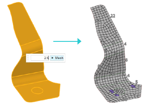
- From the guide bar, click Mesh.
Adjust Mesh
-
If necessary, select the tool from the 2D ribbon.
Figure 5. 
-
Set the density of the edges shown in Figure 6 to 12.
- Hover over an edge with a density of 12 and press to copy its settings.
- Hover over an edge you wish to change and press to paste the settings.
- If necessary, select Update from the guide bar.
Figure 6. 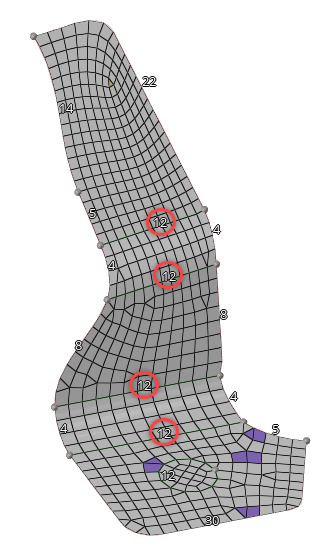
Tip: From the guide bar, click and select
Auto update to automatically update the mapped
surface. -
Select the tool from the 2D ribbon.
Figure 7.
-
In the modeling window, select the two surfaces
highlighted in Figure 8.
Figure 8. 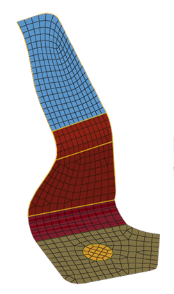
- In the microdialog, set Element type to Quads only.
- Select the Map Type tab, and verify Map as is set to Rectangle.
-
From the Topology ribbon, select the tool.
Figure 9. 
-
Left-click and drag to create a line to split the surface.
Figure 10. 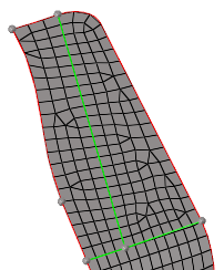
-
Left-click to create two fixed points.
Figure 11. 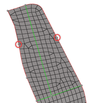
-
From the 2D ribbon, select the tool.
Figure 12.
-
In the modeling window, select the two surfaces and
click Mesh from the guide bar or
microdialog.
Figure 13. 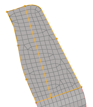
-
If necessary, select the tool from the 2D ribbon.
Figure 14.
-
Set the edges density as shown in Figure 15.
Figure 15. 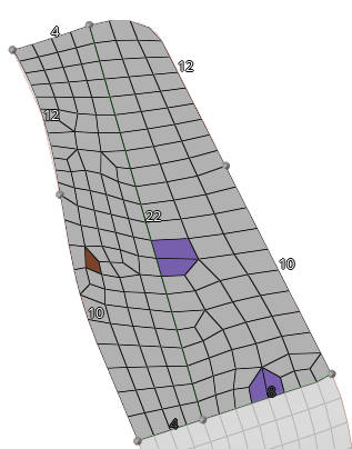
-
Select the tool from the 2D ribbon.
Figure 16.
- In the modeling window, select the right part.
- In the microdialog, verify Element type is set to Quads only.
- Select the Map Type tab, and set Map as to Triangle.
- Exit the tool.
Edit Mesh
-
From the Topology ribbon, select the tool.
Figure 17.
-
Left-click and drag to create lines to split the surface as shown in Figure 18.
Figure 18. 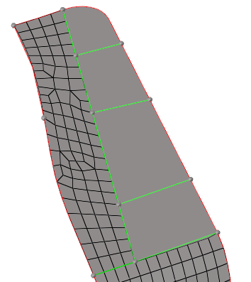
-
From the 2D ribbon, select the tool.
Figure 19.
-
In the modeling window, select the four surfaces and
click Mesh from the guide bar or
microdialog.
Figure 20. 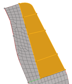
-
If necessary, select the tool from the 2D ribbon.
Figure 21.
-
Set the edges density as shown in Figure 22.
Figure 22. 
Note: Your edge density may be slightly different. Adjust the edge density to obtain a regular mesh as shown in the images. -
Select the tool from the 2D ribbon.
Figure 23.
-
In the modeling window, select the surfaces highlighted
in Figure 24.
Figure 24. 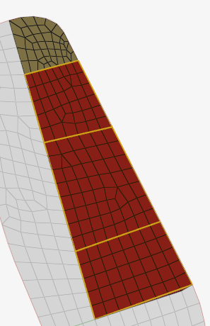
- In the microdialog, verify Element type is set to Quads only.
- Select the Map Type tab, and verify Map as is set to Rectangle.
-
In the modeling window, select the surface shown in
Figure 25.
Figure 25. 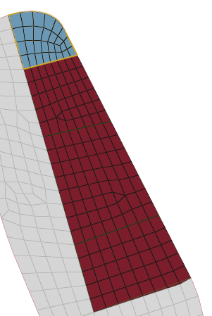
- In the microdialog, verify Element type is set to Quads only.
- Select the Map Type tab, and set Map as to Triangle.
- Exit the tool.