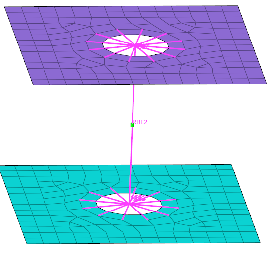
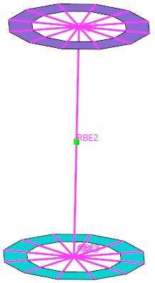
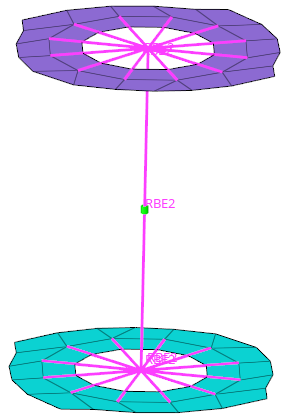
Connector Entity Browser
The Connector Entity Browser contains a list of all the connections contained in the model, and has its own set of tools similar to the ones found in the Link Entity Browser.
All the connectors in the model are displayed in folders organized by tabs based on the respective type. The All Tab contains a list view of the connectors in the model. Each type of connector has its own tab with a flat list of connectors.
The connector information in the specific tabs can be used to find link entities connected by specific connectors, and also to modify certain connector attributes. The columns display a sub-set of connector information that is important for recognizing connection information easily.
- General – all of the links are within the same subsystem
- Subsystem – one or all of the links are in multiple subsystems
- Attachment – a new single lined connector entity
- 1st connector entity
- Selected connectors.
- linked entities
- Links which are referenced by one of the selected connectors.
This kind of categorical separation is only used for the actions show, hide, isolate and isolate only, and only when one of the view option toggle buttons is active, regardless of whether the actions are taken from the context menu. No other functionality uses this categorization at all.
You can also change the base features of the Connector Entity Browser in the Connector Entity Browser configuration window.
| Option | Description |
|---|---|
| Entities | ID of the connector and an image that represents the respective connector’s style (spot, seam, bolt, and so on). |
| Status | Realization state of the connector entity:
unrealized, realized,
failed, or
modified. Note: For those writing scripts
instead of using the GUI, a more detailed report can be
created by using the following lines in your script: set
error_report [ hm_ce_errorreport CE_ID 1 ].
|
| Tolerance | Realization tolerance of the connector. You can change this by right-clicking the field and typing in a new value, then pressing Enter. |
| Link | ID or name of the entity added as a link to a connector. |
| Layer | Total number of link entities to be joined by the connector. This is also marked as thickness layers (2T/3T/4T, and so on). |
| Subsystem | Displays connectors associated with a subsystem. |
| Connector Group | Name of the Connector Group to which the connector belongs. |
| Comment | Input comments for a connector. |
| Error Message | Error messages for a connector. |
Functionality is accessed from the global display tool set, an action modes tool set and a right-click context menu.
View Option Toggle Buttons
These options determine the entities that display when you select and then show, hide, or isolate a supported entity.

Each button is modal, that is, you click it once to activate it, and click it again to deactivate it. Active buttons remain active until you specifically deactivate them, so you do not need to worry about them "resetting" after you perform an action such as isolate.

| Option | Name | Effect |
|---|---|---|
| Linked entity | Finds the link entities/supported entities to which the
selected connector connects. If this linked entity view option button is active, all entities linked to the 1st connector entities will be taken into account for the action. It does not matter if the 1st connector entity view option button is active or inactive, its entities will still be located. This determination has nothing to do with any display states. This means that in case of isolation, only the
entities which are referenced by the selected connectors
(1st connector entity) are isolated.  |
|
| Realization | Finds and displays the realization for the selected
connectors. |
Cumulative Effect of Multiple View Options
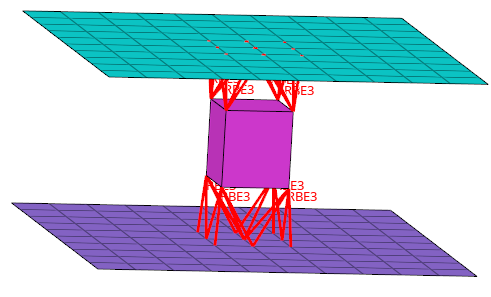
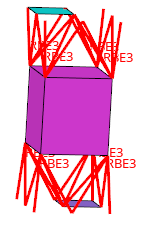
These options work accumulatively, for example, when both the Linked entity and 2nd connector entity buttons are active, then selecting and isolating a connector displays the component that it links to, and all the other connectors that link to that component. If you had Realization, Linked entity, and 2nd connector entity active when you isolated the same connector, then the model would display the component to which the connector links, all other connectors linking to that component, and the realizations of each displayed connector.
Context Menu
Configuration Window
In the Browser Configuration dialog you can select which columns to display in the browser, and change the way special tools, such as find twin connectors, operate.
Open the Browser Configuration dialog by right-clicking in the Connector Entity Browser and selecting Configure Browser from the context menu.
Local Options
- Max Link Column Viewed
- Regardless of how many links a connector might have, the browser will only display the specified number of columns.
- Show Primary Links Only
- By default, both primary and secondary links are displayed in the browser. To only display primary links, select the Show Primary link only checkbox.
- Show Node Attachment Label
- Show the name of the node attachment in the graphics area.
- Auto-Create Parts for Realization
- Create parts in Part Browser to hold the realization component nested under a part configuration.
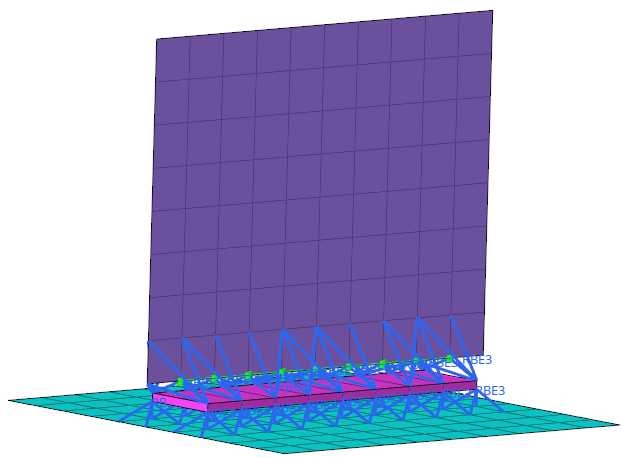
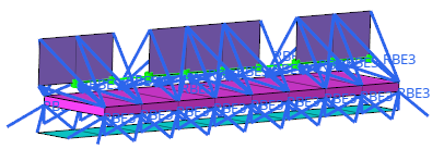
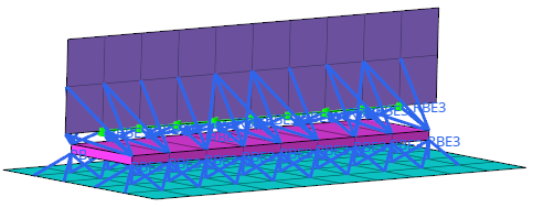
- Consider Geometry
- Consider geometry along with elements while using Show/Hide/Isolate
operations.
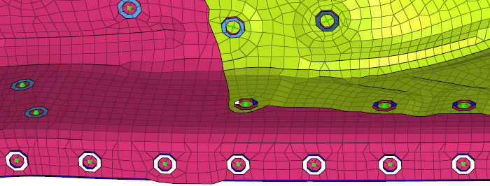
Figure 6. Consider Geometry: Off 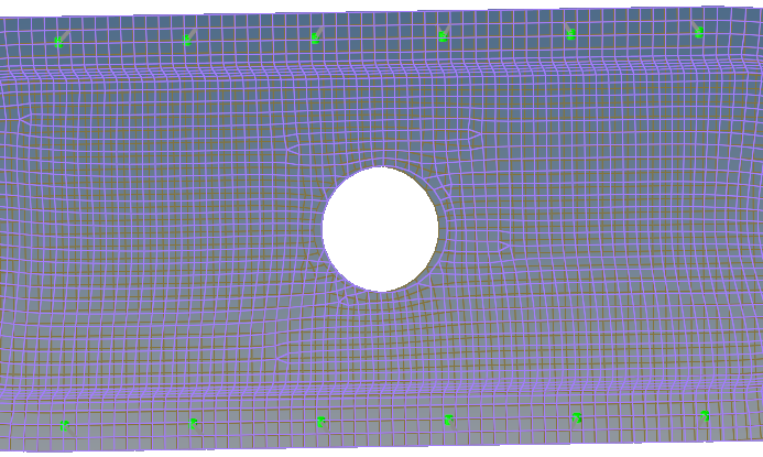
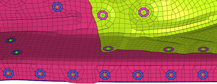
Figure 7. Consider Geometry: On 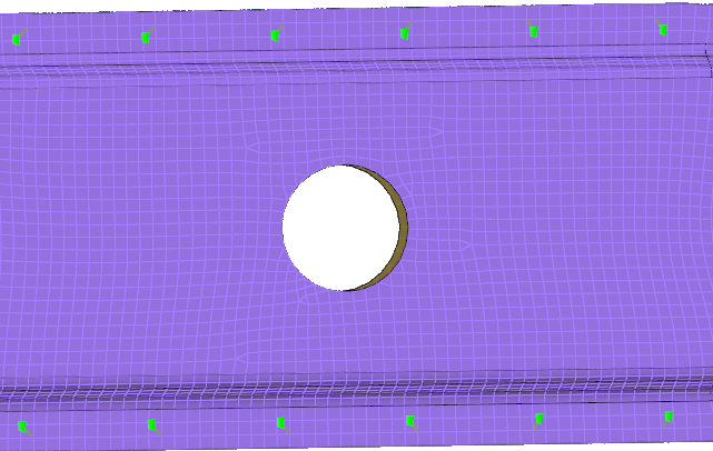
- Consider HAZ Elements
- Consider HAZ elements while using Show/Hide/Isolate operations. When this option is on, and if connectors are isolated, HAZ elements are also isolated along with connectors and their links.
- Find Connectors Between With
- Select how connectors between selected links are found:
- Minimum two selected links
- Only connectors that link to at least two selected entities will be affected. Connectors with only one link to any of the selected entities will be ignored.
- Exact selected links
- Only connectors that link to the selected entities will be affected. This can vary from the Minimum two selected links option, because connectors with three or more links which link two selected entities with at least one unselected entity, would still be found by the Minimum two selected links option but not by this one.
- All selected links
- Any connector shared by the selected entities will be
found.Note: Connectors which link selected entities to any unselected ones will not be found, as they are not located between the selected entities.
- Filter Links To
- Choose which links to filter when performing search/isolation
functions.
- Projection Components
- Isolate the entire link component.
- Projection Elements
- Isolate only the elements on which a projection falls.
- Projection and Attached Elements
- Isolate only the elements on which the projection falls and the elements which the connector FE connects.
Global Options
- Autocolor Visualization Mode
- Automatically switch the element color mode when accessing different tabs in the Connector Link Entity Browser.
- Live-filtering
- Filter items in real time.

