Link Entity Browser
The Link Entity Browser displays all of the links that are connected using the connectors in the model.
The information displayed in this browser can be used to quickly locate certain links and appropriate connectors in the graphics area.
- 1st link entity
- Selected links
- Linked connectors
- Connectors which reference at least one of the selected links
- 2nd link entity
- Links which are referenced by the linked collectors
HyperMesh only uses this type of categorical separation when one of the view options are active and you select the show, hide, isolate, and isolate only options from the context menu. No other functionality uses this categorization at all.
The base features in the Link Entity Browser can be changed from the Link Entity Browser configuration window.
View Option Toggle Buttons
The Link Entity Browser is a tool to easily examine the connections between the different parts of a model. One strategy to do that is to start the investigation on one part or a certain group of parts, so each action in the Link Entity Browser starts with a selection of parts. Parts can be considered as links.
Each button is modal, that is, you click it once to activate it, and click it again to deactivate it. Active buttons remain active until you specifically deactivate them, so you do not need to worry about them "resetting" after you perform an action such as isolate.
| Option | Name | Effect |
|---|---|---|
| Linked connector entity | If this linked connector entity view option button is active
all connectors linked to the 1st link entities will be taken
into account for the action. It does not matter if the 1st link
entity view option button is active or inactive, its connectors
will still be located. This determination has nothing to do with
any display states. This means that in case of the isolation,
only the connectors which are referenced by the selected
links (1st link entity) are isolated.  |
|
| Realization | When this option is active, all realizations belonging to the
determined linked connector entities will be taken into account
for the action. |
Cumulative Effect of Multiple Options
These options work accumulatively, for example, when both the 1st link entity and 2nd link entity buttons are active, then selecting and isolating a component link displays both it and all of the components connected it. If you had realization, 1st link entity, and 2nd link entity active when you isolated the same component link, then the model would display all of the component links connected to the selected one, as well as graphical representation of the realizations of each connector linking those component links together.
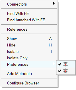
Context Menu
Right-click on an empty space or right-click on an entity to access the context menu. The options in the context menu vary accordingly.
| Option | Description |
|---|---|
| Create | Create a new Connector Group. |
| Reorganize |
|
| Show All | Turn on the display state of all entities. |
| Show None | Turn off the display state of all entities. |
| Reverse | Reverse the display state of all entities. |
| Configure Browser | Opens the Configuration Window dialog. |
| Option | Description |
|---|---|
| Duplicate | Create a new, empty Connector Group. If Duplicate is used on a Connector Group that has the name “Connector_Group_1”, a new, empty Connector Group with the name “Connector_Group_11” is created. |
| Rename | Rename a Connector Group. |
| References | Open the Reference Browser and review a list of all Connectors Groups and Connectors that belong to that Connector Group. |
| Delete | Delete selected entity. In the Confirm dialog, select the Retain Connectors and move to Model checkbox to only delete the Connector Group, and move the connectors that belong to the deleted Connector Group to the Model. By default, both the Connector Group and all the connectors that belong to the Connector Group are deleted. |
| Empty | Open the Delete Entity dialog, from which you can choose which empty Connector Groups to delete. |
| Configure Browser | Opens the Configuration Window dialog. |
| Option | Description |
|---|---|
| Convert Links(s) | Convert existing link type on connectors to: Part, Comp, or
Prop. Connector link conversion requires a clear 1:1 relation between a component and a property, otherwise the conversion is not unique and cannot be performed. |
| Remove From Connectors | Remove links from connectors. This option works on selected/displayed/all connectors. Use the update layer option to automatically update layers once links are removed. |
| Find / Find with FE | The selected links and all connectors referencing them are
isolated in the graphics area. The links as well as the linked
connectors are highlighted in their browsers. This Find
operation considers only the realization and fit view
buttons. When the realization button |
| Find Attached / Find Attached with FE | The selected links, all connectors referencing them, and all
links referenced by these connectors are isolated in the
graphics area. All the found links as well as the linked
connectors are highlighted in their browsers. This Find
Attached operation considers only the realization and fit
view buttons. When the realization button |
| Find Between / Find Between with FE | The selected links and connectors that link them together are
isolated in the graphics area. All the found links as well as
their shared connectors are highlighted in their browsers. This Find Between operation
considers only the realization and fit view buttons. When
the realization button Note: The type of connector to find by
this action can be set in the options tab of the
Link Entity Browser
Configuration dialog. By default, a
connector which references at minimum two of the
selected links is treated as a "between"
connector. |
| Show | Shows selected entities. |
| Hide | Hides selected entities. |
| Isolate | Displays only the selected
entities, turning their display state to on and turning all
other entities of the same type off. Isolate works locally
within a specific entity type – for example, if component(s)
are isolated, then all display states of other displayable
entities, such as load collectors, remain
untouched. Tip: Only show the isolated links
in the browser by selecting
(last_celink_review) from the
query build drop-down menu. |
| Isolate Only | Works like Isolate, except that it also affects entity types different from the matching, selected entities. Thus, it turns off ALL displayable entities, regardless of type, except for the selected one(s). |
| Column Visibility | Opens the Column Visibility dialog. Checkboxes are used to control, which columns should be shown in the browser. |
| Configure Browser | Opens the Configuration Window dialog. |
Configuration Window
In the Browser Configuration dialog you can alter the columns that display in the Link Entity Browser, and change how special features, such as the find between, operate.
Access the Browser Configuration dialog by right-clicking in the Link Entity Browser and selecting Configure Browser from the context menu.
Local Options
- Max Link Column Viewed
- Only display the specified number of columns, regardless of how many links are available in a connector. The maximum number of supported columns is 30.
- Show Primary Links Only
- By default, both primary and secondary links are displayed in the Connector Entity browser. To only display primary links, select the Show Primary link only checkbox.
- Consider Geometry
- Consider geometry along with elements while using Show/Hide/Isolate
operations.
Figure 5. Consider Geometry: Off 
Figure 6. Consider Geometry: On 
- Consider HAZ Elements
- Consider HAZ elements while using Show/Hide/Isolate operations. When this option is on, and if connectors are isolated, HAZ elements are also isolated along with connectors and their links.
- Available for Connector Configure browser options.
Figure 7. Consider HAZ Elements: Off. HAZ elements of hexa Nugget connectors are not isolated along with connectors and linked components. 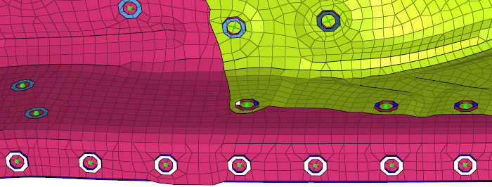
Figure 8. Consider HAZ Elements: On. HAZ elements of hexa Nugget connectors are isolated along with connectors and linked components. 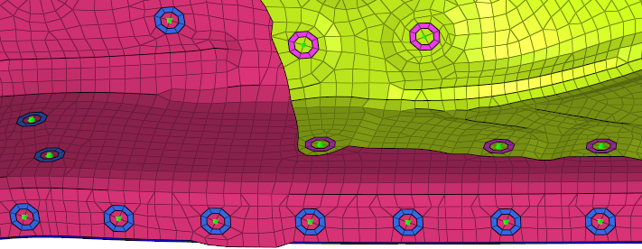
- Find Twin Connectors
- Select how two connectors are found:
- Minimum two links
- Find only the connectors that have two or more matching links.
- Exact links
- Find only the connectors that have the same links. For example, if you start with a connector that has two links, than another connector with three links will not be found even if its first two links matched.
- Find Connectors Between With
- Select how connectors between selected links are found:
- Minimum two selected links
- Only connectors that link to at least two selected entities will be affected. Connectors with only one link to any of the selected entities will be ignored.
- Exact selected links
- Only connectors that link to the selected entities will be affected. This can vary from the Minimum two selected links option, because connectors with three or more links which link two selected entities with at least one unselected entity, would still be found by the Minimum two selected links option but not by this one.
- All selected links
- Any connector shared by the selected entities will be
found.Note: Connectors which link selected entities to any unselected ones will not be found, as they are not located between the selected entities.
- Filter Links To
- Choose which links to filter when performing search/isolation
functions.
- Projection Components
- Isolate the entire link component.
- Projection Elements
- Isolate only the elements on which a projection falls.
- Projection and Attached Elements
- Isolate only the elements on which the projection falls and the elements which the connector FE connects.
-
Filter Links To Projection Components Projection Elements Projection and Attached Elements Spots Figure 9. 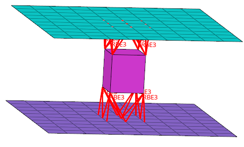
Figure 10. 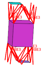
Figure 11. 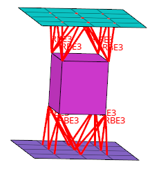
Seams Figure 12. 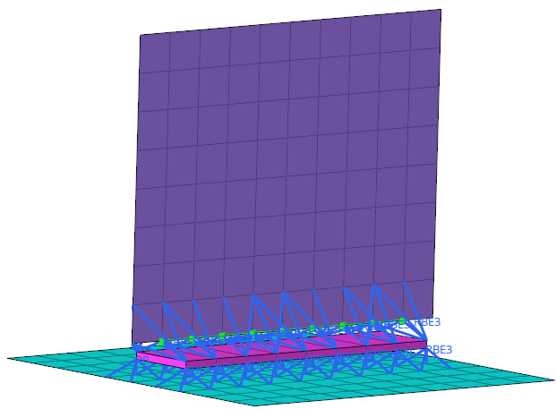
Figure 13. 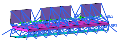
Figure 14. 
Bolts Figure 15. 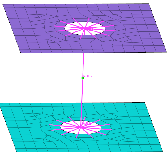
Figure 16. 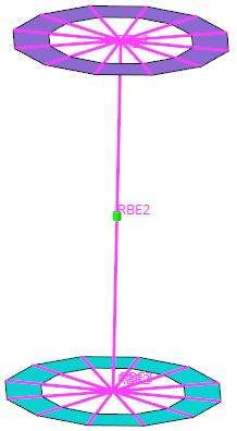
Figure 17. 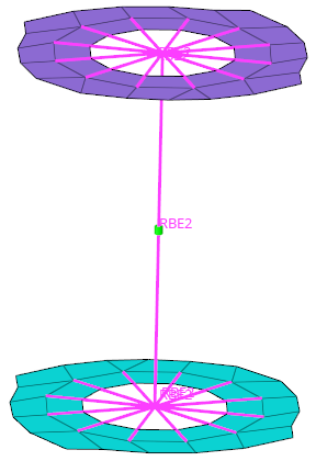
Global Options
- Autocolor Visualization Mode
- With this mode activated, the Connector Browser takes over the control of the element visualization mode. Elements will be colored by component, by property, or by part, depending on which connector link view is activated.
- Live-filtering
- Filter items in real time.