Model BrowserでComponentsを右クリックし、context menuから<uicontrol>Representation</uicontrol>Isolate Onlyを選択します。
Standard Viewsツールバーでをクリックし、モデルを画面いっぱいに表示させます。
コンポーネントのみが表示されます。
Create Topology Design Variables
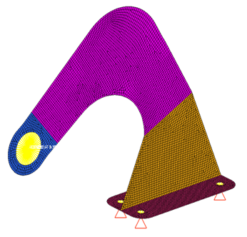
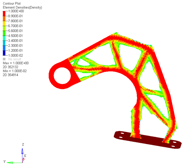
In this step you will set the optimization to optimize the shell
elements in the Design and Base components to create structural members with minimum
member size of 1.0 unit in width with thicknesses that vary between zero and the
thickness of the shell. The optimization will use 1000 as the maximum stress for any
element within the design region when validating the design.
From the Analysis page, click optimization.
Click topology.
Select the create subpanel.
In the desvar= field, enter shells.
Set type: to PSHELL.
Using the props selector, select Design and Base.
Click create.
Update the design variable's parameters.
Select the parameters subpanel.
Toggle minmemb off to mindim=, then enter
1.0.
Under stress constraint, toggle none to stress=
and enter 1000.
Click update.
Click return.
Create Optimization Responses
From the Analysis page, click optimization.
Click Responses.
Create the mass response, which is defined for the total volume of the
model.
In the responses= field, enter mass.
Below response type, select mass.
Set regional selection to total and
no regionid.
Click create.
Click return to go back to the Optimization panel.
Click return twice to exit the Optimization panel.
データベースの保存
menu barでFile > Save As > Modelをクリックします。
Save Asダイアログでファイル名欄にhook_opt.hmと入力し、自身の作業ディレクトリに保存します。
Run the Optimization
From the Analysis page, click OptiStruct.
Click save as.
In the Save As dialog, specify location to write the
OptiStruct model file and enter
hook_opt for filename.
For OptiStruct input decks,
.fem is the recommended extension.
Click Save.
The input file field displays the filename and location specified in the
Save As dialog.
Set the export options toggle to all.
Set the run options toggle to optimization.
Set the memory options toggle to memory default.
Click OptiStruct to run the optimization.
The following message appears in the window at the completion of the
job:
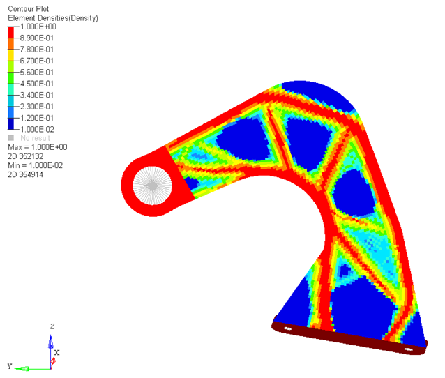
OPTIMIZATION HAS CONVERGED.
FEASIBLE DESIGN (ALL CONSTRAINTS SATISFIED).
OptiStruct also reports error messages if any exist. The
file hook_opt.out can be opened in a
text editor to find details regarding any errors. This file is written to the
same directory as the .fem file.

 を選択します。
Select OptiStruct Fileブラウザが開きます。
を選択します。
Select OptiStruct Fileブラウザが開きます。 をクリックし、モデルを画面いっぱいに表示させます。
 をクリックし、Contour panelを開きます。
 をクリックし、Iso Valueパネルを開きます。
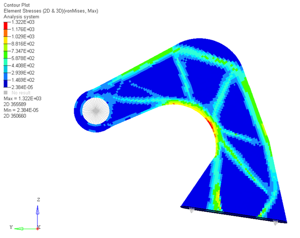
 をクリックし、Subcase 1の線形静解析からの結果を表すページに移動します。
このページの結果はhook_opt_s19.h3dから読み込まれ、最初のサブケースの線形静解析結果が含まれています。
をクリックし、Subcase 1の線形静解析からの結果を表すページに移動します。
このページの結果はhook_opt_s19.h3dから読み込まれ、最初のサブケースの線形静解析結果が含まれています。