Skew
Overview
 |
|
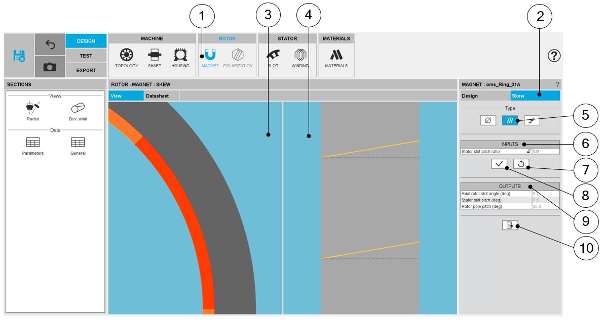
| BAR – SKEW design area | |
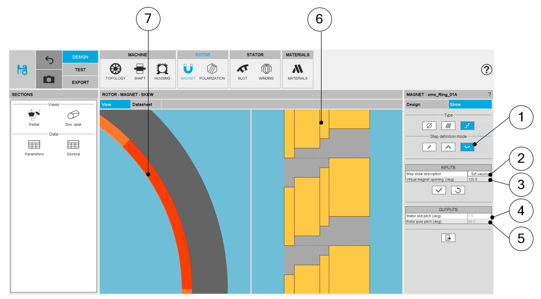
| 1 | Selection of the ROTOR subset: MAGNET panel (Click on the icon MAGNET). |
| 2 | SKEW tab indicates the tools to define the rotor (magnet) skewing angle. |
| 3 | Visualization of the motor radial view with bar topology and dimensions. |
| 4 | Visualization of the rotor developed view to visualize the rotor (magnet) skewing. |
| 5 | Choices to define a skew: None – Continuous (Continuous in our example). |
| 6 | Skew inputs to be defined. |
| 7 | Buttons to restore the default input values. |
| 8 | Buttons to validate the inputs (Pressing the “enter key” twice applies inputs too). |
| 9 | Skew outputs (read only). |
| 10 | Button to export the skew data into *.txt or *.xls files. |
Continuous skew
Set a skew angle
 |
|
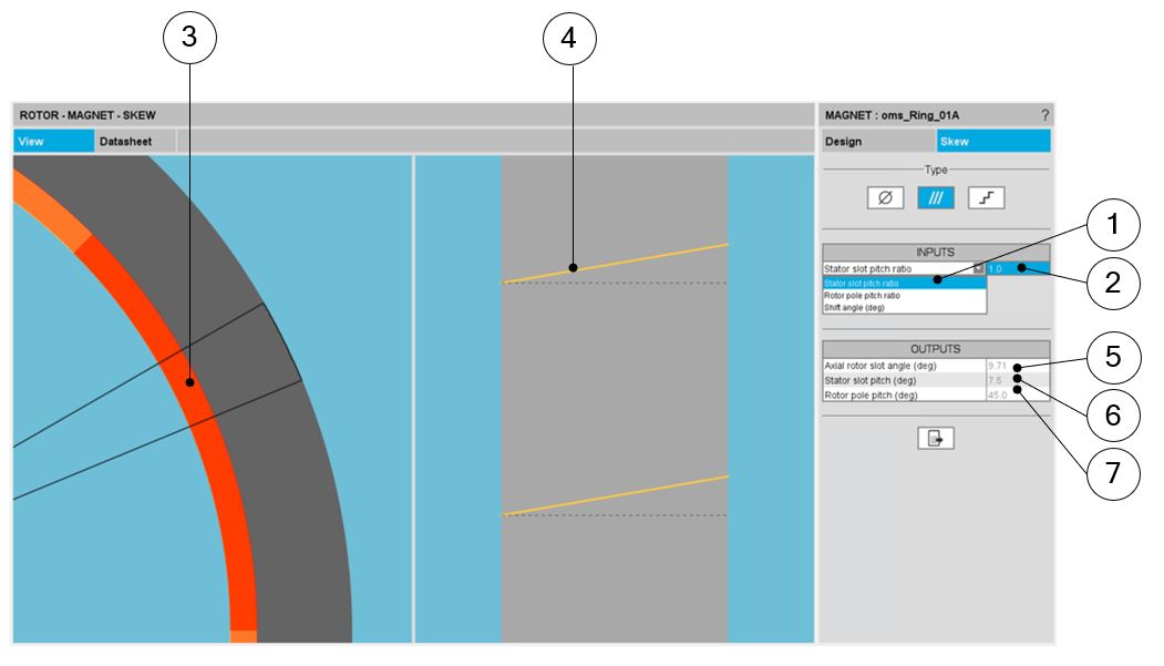
| How to set a skew angle? | |
| 1 | Choose the definition mode of the skew:Stator slot – Rotor slot – Shift angle. |
| 2 | Definition of the skew angle depending of the definition mode. |
| 3 | Visualization of the chosen skew angle on the machine radial view. |
| 4 | Visualization of the equivalent axial slot angle on the rotor developed view. |
| 5 | Equivalent axial rotor slot angle (read only). |
| 6 | Equivalent stator slot pitch (read only). |
| 7 | Equivalent rotor slot pitch (read only). |
Note: The user can add a skew angle on the rotor or on the stator. If
a skew is already defined in the stator when setting a skew on the rotor, the stator
skewing will be automatically reset to “None”.
Step skew
Linear step skew
 |
|
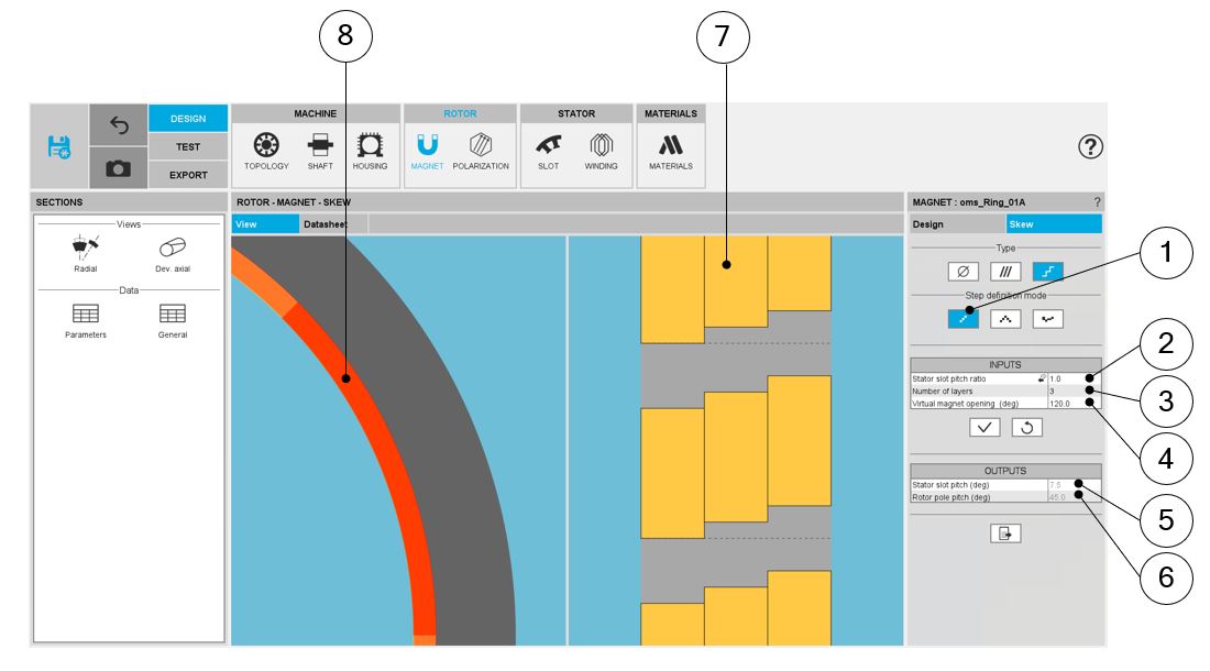
| How to define a linear step skew? | |
| 1 | Linear step skew definition mode |
| 2 | Choose the definition mode of the skew:
|
| 3 | Number of layers |
| 4 | Virtual magnet opening to adjust the axial view to any size of magnet opening |
| 5 | Equivalent stator slot pitch (read only) |
| 6 | Equivalent rotor slot pitch (read only) |
| 7 | Visualization of the chosen skew angle on the machine radial view |
| 8 | Visualization of the rotor developed view resulting from the axial slot angle, the number of layer and the virtual magnet opening |
Note: The user can add a skew angle on the rotor (continuous or
step) or on the stator (continuous). If a skew is already defined in the stator when
setting a skew on the rotor, the stator skewing will be automatically reset to
“None”.
V shape
 |
|
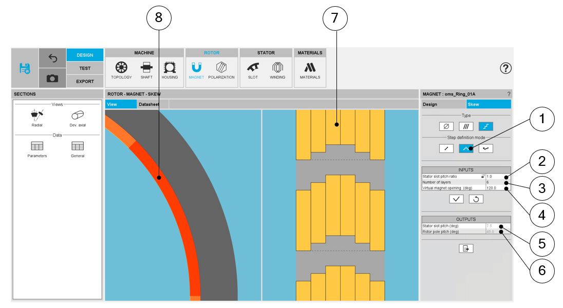
| How to define a V shape step skew? | |
| 1 | V shape step skew definition mode |
| 2 | Choose the definition mode of the skew:
|
| 3 | Number of layers |
| 4 | Virtual magnet opening to adjust the axial view to any size of magnet opening |
| 5 | Equivalent stator slot pitch (read only) |
| 6 | Equivalent rotor slot pitch (read only) |
| 7 | Visualization of the chosen skew angle on the machine radial view |
| 8 | Visualization of the rotor developed view resulting from the axial slot angle, the number of layer and the virtual magnet opening |
Note: The user can add a skew angle on the rotor (continuous or step)
or on the stator (continuous). If a skew is already defined in the stator when setting a
skew on the rotor, the stator skewing will be automatically reset to “None”.
Customized skew
 |
|
| How to define a customized step skew? | |
| 1 | Custom step skew definition mode |
| 2 | Click in the button “Set values” of the field “Step skew description” to
open a dialog box to define the custom step skew. Refer to the next illustration which shows how to fill the Custom step skew table. |
| 3 | Virtual magnet opening to adjust the axial view to any size of magnet opening |
| 4 | Equivalent stator slot pitch (read only) |
| 5 | Equivalent rotor slot pitch (read only) |
| 6 | Visualization of the chosen skew angle on the machine radial view |
| 7 | Visualization of the rotor developed view resulting from the axial slot angle, the number of layer and the virtual magnet opening |
 |
|
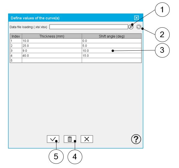
| Step skew description – Dialog box to define the custom step skew | |
| 1 | Dialog box opened after having clicked on the button “Set values” in the field “Step skew description”. |
| 2 | Browse the folder to select an Excel file which is described the custom step skew configuration. |
| 3 | Button to refresh the table data when the considered Excel file has been modified. |
| 4 | Fields to be filled with data to describe the step skew configuration to be considered. |
Note: The first value of the shift angle must be “0”
Note: The shift angle of each layer (or index) refers to the
reference axis given by the dash line in the axial view (position of the first layer).
Note: The sum of the thickness of each layer must be egal to the
rotor length.
Note: The user can add a skew angle on the rotor (continuous or
step) or on the stator (continuous). If a skew is already defined in the stator when
setting a skew on the rotor, the stator skewing will be automatically reset to “None”.