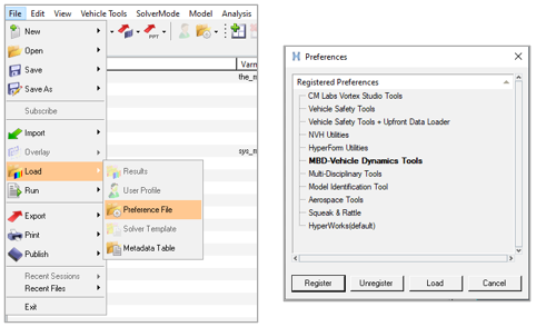
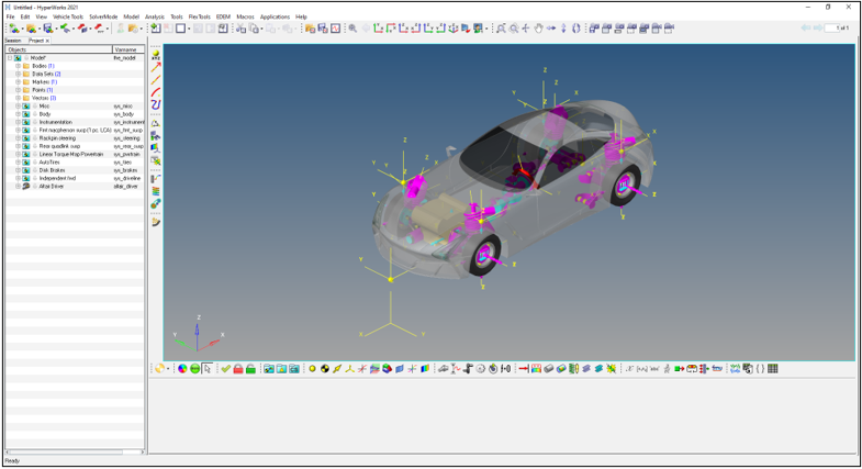
When you build a car/light truck mode using the Assembly Wizard, you can select to include
Anti-Lock-Braking. The Anti-Lock Braking MotionView system
collects information like wheel speeds, vehicle longitudinal acceleration, front and rear
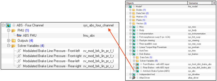
master cylinder pressure, and brake pedal switch from the MotionView model as input to the ABS Twin Activate Model imported into MotionView as a Functional Mock-up Unit
(FMU). The ABS Twin Activate Model estimates the wheel slips and when
impending wheel lock occurs under braking outputs modulated hydraulic pressure for each
brake caliper to the MotionView ABS system. The MotionView ABS system then outputs those pressures MotionView brake system. The Anti-Lock Braking Altair Twin Activate model (.scm file) is included in the MDL
Library for viewing and editing
(…\hwdesktop\hw\mdl\mdllib\Common\FMU_Library\ABS). The figure below
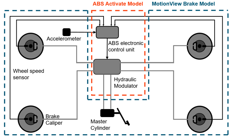
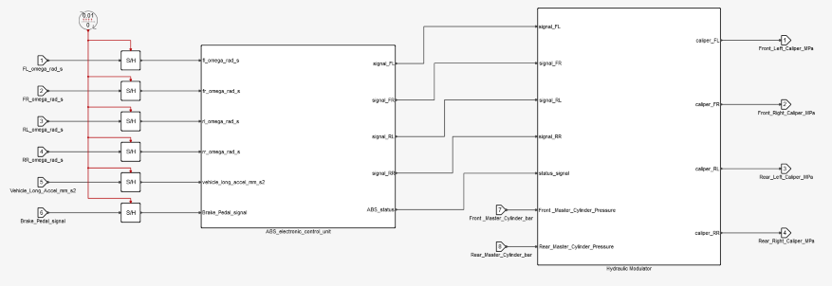
shows the schematic relationship between the ABS Twin Activate Model
and the MotionView Brake.Figure 1.
The following sections describe the ABS Twin Activate Model and how
to use the Assembly Wizard to build a vehicle model that includes ABS.
ABS Twin Activate Model
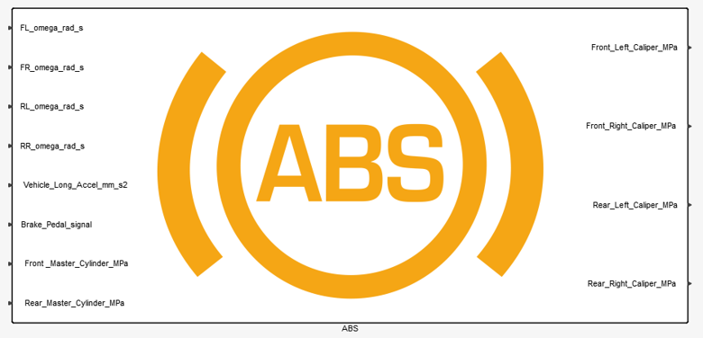
In Altair Twin Activate the Anti-Lock Braking System is a super
block (as shown below) with the input ports on the left and outputs ports on the right side
of the block.Figure 2.
All of the inputs represent sensors signals, except the front and rear master cylinder
hydraulic pressures which are needed to model the physics of the flow through the hydraulic
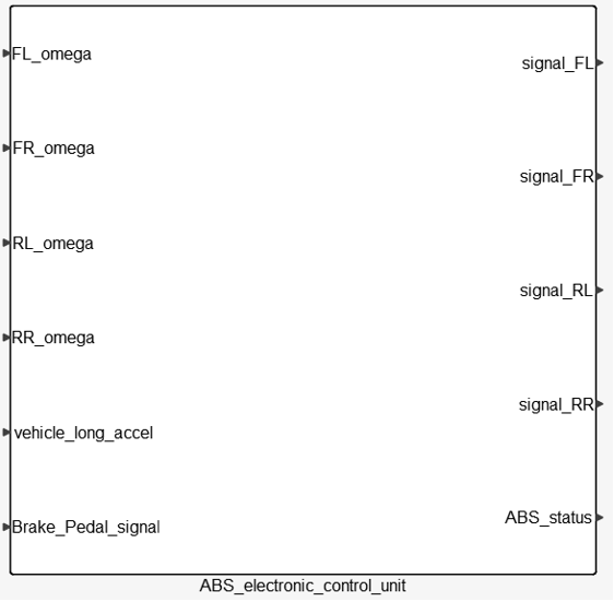
control valves. Expanding the ABS super block as shown in the figure below reveals two major
sub-blocks: the ABS Electronic Control Unit and the Hydraulic Modulator. Each sub-block is
described independently below.Figure 3.
ABS Electronic Control Unit
The ABS Electronic Control Unit estimates the wheel slips and determines whether to
modulate the hydraulic pressure and then sends control signals to the Hydraulic
Modulator. Figure 4.
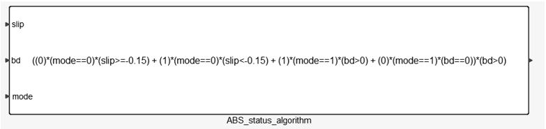
Most ABS control algorithms use bang-bang control abruptly switching between
states. The ABS controller here switches between three states: “apply”, “hold” or
“release” pressure. The controller estimates the wheel slip ratio and wheel angular
acceleration and then outputs the desired valve state signal in accordance with the
following algorithm:
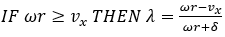
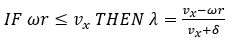
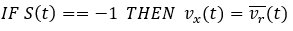
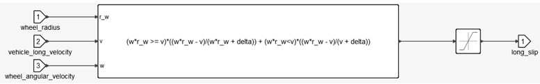
Wheel slip is estimated from the wheel rotational velocity and the
vehicles longitudinal velocity as:
Where:
: wheel slip
: wheels rotational velocity
: vehicle’s longitudinal velocity
: tires radius
: a small number
Figure 5.
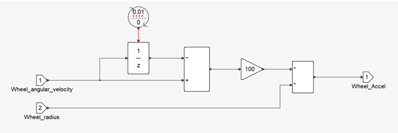
The wheel's angular acceleration is calculated using wheels rotational
velocity as:
Figure 6.
Where is the sampling time of sensors.
The vehicle’s
longitudinal velocity used in slip calculation refers is estimated from the wheel
speeds and vehicle’s longitudinal acceleration.Figure 7.
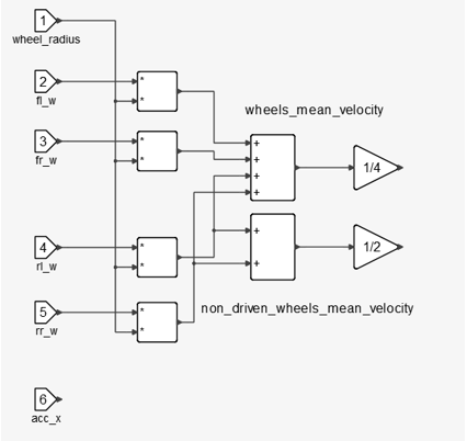
Each sampling instant three auxiliary signals are computed:
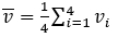
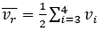
Average wheel speed of the four tires
Average wheel speed of the two non-driven tires
Longitudinal Acceleration
Figure 8.
Estimation algorithm behavior changes according to the status of
vehicle which can be represented by four values:
Vehicle's velocity is very low
Vehicle is accelerating
Vehicle has constant velocity or decelerating
softly
Vehicle is decelerating
Status is computed based on previous step status and some threshold
values alongside with some hysteresis in order to keep the algorithm stable.
Figure 9.
Velocity estimation based on the current status of the vehicle is:
Finally, the ABS Electronic Control Unit is also responsible to trigger
ABS. This happens after a significant amount of wheel slip occurs. Here the
electronic control unit works as a switch specifying if brake pressure is controlled
by ABS module.
Figure 10.
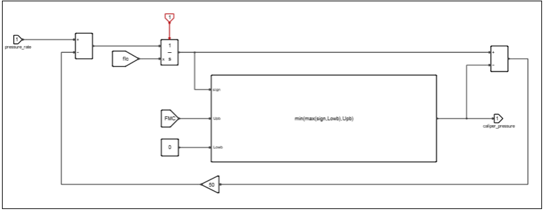
Hydraulic Modulator
The Hydraulic Modulator is the actuator of the brake system. When a signal is
generated, it’s responsible for changing pressure according to the signal. In normal
conditions master cylinders pressure is acting on calipers. When ABS
is activated caliper pressure is reduced, hold, or increased at a
certain rate. Figure 11.
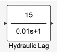
Pressure rate is modeled in Twin Activate as a first
order transfer function where denotes the magnitude of pressure change rate and is the time delay of the valve to reach its steady
condition. Figure 12.
Finally, an integrator is used in order to change the applied pressure
on the caliper. This integrator is simulating caliper’s pressure, so it needs to be
correctly initialized and saturated. For its initialization an event trigger is used
which tracks the activation of ABS. For its saturation an anti-windup integrator was
designed so the ABS cannot exceed master cylinder pressure given from the
driver.Figure 13.
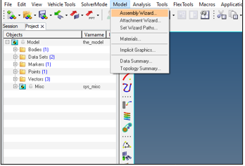
Create a Vehicle Model with ABS
Follow the steps below to create a full vehicle model with ABS.
 : wheel slip
 : wheels rotational velocity
 : vehicle’s longitudinal velocity
 : tires radius
 : a small number
 is the sampling time of sensors.The vehicle’s longitudinal velocity used in slip calculation refers is estimated from the wheel speeds and vehicle’s longitudinal acceleration.
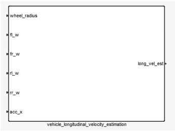

 Vehicle's velocity is very low
 Vehicle is accelerating
 Vehicle has constant velocity or decelerating
softly
Vehicle has constant velocity or decelerating
softly Vehicle is decelerating
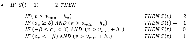

 master cylinders pressure is acting on calipers. When ABS
is activated
master cylinders pressure is acting on calipers. When ABS
is activated  caliper pressure is reduced, hold, or increased at a
certain rate.
caliper pressure is reduced, hold, or increased at a
certain rate. 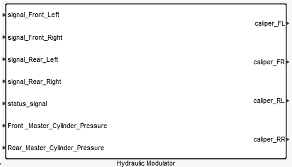
 where
where  denotes the magnitude of pressure change rate and
  is the time delay of the valve to reach its steady
condition.
is the time delay of the valve to reach its steady
condition.