Edit Contacts
Contact properties can be edited using the Entity Editor. Checks on graphics for suitability for contacts can also be performed.
Contact Properties
| Property | Description | |||
|---|---|---|---|---|
| General | ||||
| Label | Descriptive label for the entity. | |||
| Varname | Variable name of the entity. | |||
| ID | Integer identifier. | |||
| Active | Active state of the entity. True or False. Entity is deactivated if False. | |||
| Type | Contact type. 3D or 2D rigid to rigid or Point to Deformable Surface. Once entity is created, this property is read-only. | |||
| 3D | Contact type is 3D. It offers the following combinations of I type and J type. | |||
| I Type | Type of contact pair on the I (first) side. Body or Deformable Curve or Deformable surface. | |||
| I Body | With I Type as Body, select the body reference for the first body in the contact pair. | |||
| I Deformable Curve Graphic | With I Type as Deformable Curve, select the deformable curve graphic as the first reference in the contact pair. | |||
| I Deformable Surface Graphic | With I Type as Deformable Surface, select the deformable surface graphic as the first reference in the contact pair. | |||
| J Type | Type of contact pair on the J (second) side. Body or Deformable Curve or Deformable surface. | |||
| J Body | With J Type as Body, body reference to the second body in the contact pair. | |||
| J Deformable Curve Graphic | With J Type as Deformable Curve, select the deformable curve graphic as the second reference in the contact pair. | |||
| J Deformable Surface Graphic | With J Type as Deformable Surface, select the deformable surface graphic as the second reference in the contact pair. | |||
| Graphics | Click on Graphics to access the Contact Graphics dialog and select the I and J graphics involved in contacts. Contact with rigid bodies can have multiple graphics selected. By default, all graphics belonging to the body are selected. See the comments below. | |||
| Highlight contact side | Display the sides of graphic in contact. | |||
| Mesh errors/No mesh errors | Mesh error will be active if any of the graphics have open edges or T connections. Click this option to highlight the mesh errors. | |||
| 2D Rigid To Rigid | Contact is between two geometrical curves belonging to different bodies in a 2D plane. | |||
| I Body | Select the body reference for the first body in the contact pair. | |||
| J Body | Select the body reference to the second body in the contact pair. | |||
| Graphics | Click on Graphics to access the Contact Graphics dialog and select the I and J graphics involved in contacts. By default, all Curve graphics belonging to the body are selected. Flip Contact side - see the comments below. | |||
| Point to Deformable Surface | Contact is between a body represented as a sphere with the selected point as center and a deformable surface. | |||
| I Body | Select the body reference for the first body in the contact pair. | |||
| Origin | Select the center point of the representative sphere on the I Body. | |||
| Deformable Surface | Select the deformable surface for the contact pair. | |||
| Properties | ||||
| Normal Force | Define properties for force calculation in the normal direction of the contact. | |||
| Type | Select the method of normal force calculation. | |||
| Impact | Use the Impact method for force calculation. Applicable for 3D or 2D rigid to rigid contact. | |||
| Stiffness | Enter a stiffness value for the boundary surface interaction. (Real, positive) | |||
| Exponent | Enter a value for the Exponent on penetration depth in the
force-penetration depth characteristic of the contact
interface. For a stiffening spring characteristic, it must be greater than 1.0. For a softening spring characteristic, it must be less than 1.0. Exponent > 0 |
|||
| Damping | Enter a value (> 0.0) for the maximum Damping coefficient. | |||
| Penetration Depth | Enter a value (> 0.0) for the Penetration depth beyond which full damping is applied. | |||
| Poisson | Use the Poisson method for force calculation. Applicable for all types of contact. | |||
| Radius | Enter a value for the radius of the representative sphere on the body that the deformable surface will be contacting. (applicable for Point to Deformable surface contact only) | |||
| Penalty | Enter a value for the Penalty parameter to determine the local stiffness properties between materials. Larger values lead to reduced penetration between two bodies. | |||
| Restitution coefficient | Enter a value for the Restitution coefficient. This value represents the energy loss between the two contact bodies. The valid range for this value is between 0.0 and 1.0. A value of 1.0 represents no energy loss and perfectly elastic contact. A value of 0.0 represents a perfectly plastic contact and all energy is dissipated during contact. | |||
| Normal transition velocity | Enter a value of velocity at which full damping is applied. (not applicable for Point to Deformable surface contact) | |||
| Volume Model | Use the Volume method for force calculation. Applicable for 3D or 2D rigid to rigid contact. | |||
| Bulk Modulus | Enter the bulk modulus value. > 0.0 The bulk modulus of a substance measures the resistance of a substance to uniform compression. It is defined as the ratio of the infinitesimal pressure increase to the resulting relative decrease of the volume. | |||
| Shear Modulus | Enter shear modulus value. > 0.0 The shear modulus or modulus of rigidity is defined as the ratio of shear stress to shear strain. |
|||
| Layer depth | Enter a value for depth of material. >0.0 | |||
| Exponent | Enter a value for the exponent of the force deformation characteristic. > 0.0 | |||
| Damping | Enter a value for the damping coefficient. > 0.0 | |||
| Linear | Use a linear spring-damper model for contact force. Applicable for Point to Deformable surface contact only. | |||
| Radius | Enter a value for the radius of the representative sphere on the body that the deformable surface will be contacting. | |||
| Stiffness | Enter a value for the stiffness of the contact force. > 0.0 | |||
| Damping | Enter a value for the damping of the contact force. > 0.0 | |||
| User defined | Use a user defined formulation for the normal and friction force calculation. Applicable for all types of contact. | |||
| Radius | Enter a value for the radius of the representative sphere on the body that the deformable surface will be contacting. (applicable for Point to Deformable surface contact only) | |||
| User expr | Provide the user expression – USER() call to the subroutine with arguments. | |||
| Use local file and function name | Optional. Provide a local file and function for the sub-routine. | |||
| Local file | Select a file for the subroutine based on Function type. | |||
| Function type | Select the type of file. DLL, Python, MATLAB or Compose. | |||
| Function name | Name of the function within the subroutine file that needs to be called. | |||
|
Note: If local file and filename is not
used, solver may use the subroutine based on its default
search criteria. Refer the solver reference guide to learn
more.
|
||||
| Friction Force | Define properties for force calculation in the tangential direction of the contact. | |||
| Type | Select the type of setting for frictional force calculation. | |||
| Disabled | Friction is disabled. | |||
| Dynamic Only | Only dynamic friction or sliding friction is considered in friction calculations. The static regime and transition to sliding is ignored. | |||
| Static & Dynamic | All three regimes are considered in friction calculations: static, transition to sliding friction, and sliding friction. | |||
| MU Static | Enter a value for the static coefficient of friction, which has to be overcome by a body before it can move. > 0.0 (not applicable for Dynamic Only) | |||
| Mu Dynamic | Enter a value for the dynamic coefficient of friction that the body experiences while in motion. > 0.0 and < MU Static. | |||
| Stiction Transition velocity | Enter a value for the velocity limit below which the coefficient of friction becomes MU static. When the slip velocity is between stiction transition velocity and friction transition velocity, the coefficient of friction is in transition between the two. > 0.0 (not applicable for Dynamic Only) | |||
| Friction Transition velocity | Enter a value for the velocity above which the coefficient of friction becomes MU dynamic. When the slip velocity is between stiction transition velocity and friction transition velocity the coefficient of friction is in transition between the two. > Stiction transition velocity | |||
| Advanced | ||||
| Find precise contact event | Select this option to tell the solver to capture the first event of contact precisely. | |||
| Max. Step size scale factor | Scale factor on the maximum step size the integrator would use to capture precise contact. | |||
| Change simulation max step size | Select this option to change the maximum step size for the simulation after contact is detected. | |||
| New max step size | New maximum step size value. | |||
| Force computed at | Select the mesh location where force is computed. | |||
| Element Center | The contact detection and force calculation in MotionSolve is based on the penetration of mesh element center. This is the default setting. | |||
| Nodes | The contact detection and force calculation in MotionSolve is based on the penetration of mesh nodes. | |||
| Note & Tags | ||||
| Note | Optional descriptive note. | |||
| Attachment Candidates | Add tags for the entity to use as possible attachments to Systems/Assemblies/Analyses. | |||
- Material Inside for a graphic indicates the
graphic has material within the closed volume. Consequently, the surface
normals of the geometry point outward of the graphic surface. When the
option is turned off, the surface normal of the geometry points inward.
This flag is useful for reversing the surface normal to simulate
internal contact.
- The normal of the mesh should point in the direction of contact.
The side of the surface mesh, when seen such that the normal
direction points towards the viewer is the contact side. If
viewed from the opposite direction, it is referred to as the
material side. Use the Material Inside
and Highlight contact side options in the
Entity Editor to set the correct direction of contact. Below is
an example of how the Material Inside and
Highlight contact side options work:
Figure 1. 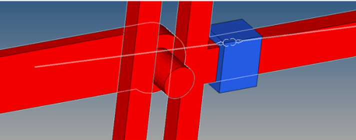
- With both of the graphics having the Material Inside option activated, checking the Highlight contact side option will display the color for both of these graphics in red when viewed from the outside of the graphics.
- The normal of the mesh should point in the direction of contact.
The side of the surface mesh, when seen such that the normal
direction points towards the viewer is the contact side. If
viewed from the opposite direction, it is referred to as the
material side. Use the Material Inside
and Highlight contact side options in the
Entity Editor to set the correct direction of contact. Below is
an example of how the Material Inside and
Highlight contact side options work:
- For 2D rigid to rigid contacts Flip Contact side
is available instead of Material Inside.
- Click Flip Contact Side to specify the side of the curve graphic which will come in contact. The side of the curve as directed by the arrow indicates its contact side. Changing this flag will reverse the direction of contact.
- In the Contact Graphics dialog, select Identify Planarity to check the planarity of the curves involved in contact. This tool checks whether the curves are planar and whether the curves are co-planar considering the first selected graphic in Body I as reference.
- The individual graphics involved in contact should form a closed volume.
In other words, the graphic mesh should not have any open edges or
T-connections. Use the Highlight mesh errors option to check for open
edges and T-connections. An open edge is highlighted through a red line,
while a T-connection is highlighted using a blue line. For better
visibility, the visualization of graphic components involved is changed
to a non-shaded mode.Note: If no mesh errors are found, this option will be disabled and will display No mesh errors.
Figure 2. 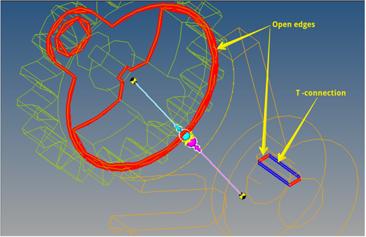
- Activating Find precise contact event will automatically introduce a sensor entity in the MotionSolve solver deck which will track the contact force function.
- As the sensor is triggered by a positive contact force, the solver rejects the last successful step and proceeds from the previous step size with a changed maximum step size. The changed maximum step size is calculated as (current max step size) * (Max step size scale factor).
- Activating Change simulation max step size will enable changing the maximum step size for the future course of the of the simulation.
- Both of the above options provide increased accuracy and robustness in contact simulations; however they will result in increased simulation times. It is therefore recommended that these options be used selectively and only when necessary.
Note on 2D Contacts
- The individual curve graphics involved in 2D contact must use planar curves only. A planar curve has all its data points in a single plane.
- Currently, MotionView only supports 3D
Cartesian/parametric curves for creating curve graphics that can be used
in 2D contact. Below is an example of how the Highlight
contact side option works:
Figure 3. 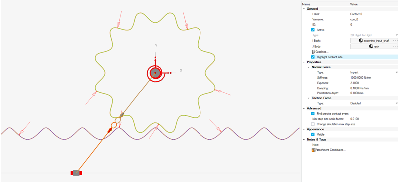
The example above shows a rack and a pinion represented with curves and a 2D contact defined between them. The side of the pinion on which the arrows are pointing (which is outside) indicates the side the contact is expected. Similarly, the arrows on the pinion curve have arrows pointing on it from the outside.
In the case where the contact is expected from the opposite side, the Flip Contact Side option can be used.