DAMPER
Overview
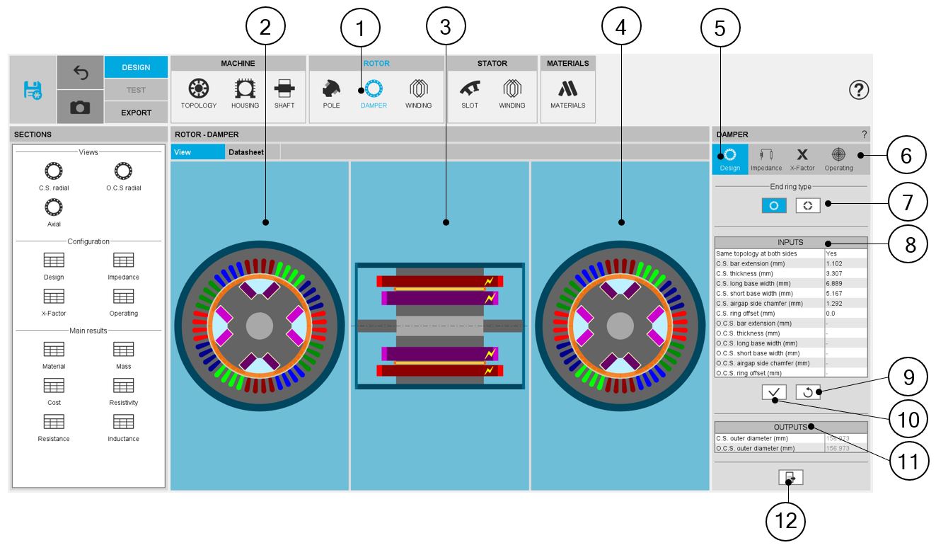
This Damper context allows designing the end rings of the damper circuit. The context is disabled if there is no bar (solid conductor) in the pole topology.
 |
|
| DAMPER - DESIGN - Overview | |
| 1 | Selection of the ROTOR subset: DAMPER panel (click on the icon DAMPER) |
| 2 | Visualization of the radial view of the machine from the Connection Side (C.S.) |
| 3 | Visualization of the axial view of the machine |
| 4 | Visualization of the radial view of the machine from the Opposite Connection Side (O.C.S.) |
| 5 |
Design settings allow for describing the dimensions of the end rings
on both sides of the machine.
Note: By default,
the DESIGN tab is selected |
| 6 |
A section scrolling bar allows choosing the section in which user inputs are defined. Scrolling selection bar where Design, Impedance, X-Factor, and Operating conditions sections can be selected. |
| 7 | Buttons to choose the end ring topology; it can be a full ring topology or a segment topology |
| 8 |
Definition of the end ring dimensions on both sides of the machine. Definition of each end ring geometrical input, with the corresponding arrow on the axial view of the machine |
| 9 | Buttons to restore default input values. |
| 10 | Buttons to apply inputs (pressing the “enter key” twice applies inputs too). |
| 11 | End ring outputs (read only) |
| 12 | Icon to export end ring data into *.txt or *.xlsx files. |