In the Model Browser, right-click on the load collector
unit-load and select Make
Current.
From the Analysis page, click load types.
Select constraint = and select
DAREA from the extended entity selection menu.
Click return to exit the Load Types panel.
Click BCs > Create > Constraints to open the Constraints menu.
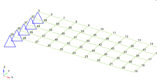
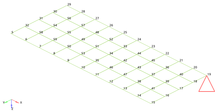
Select node number 19 on the plate by clicking on it (図 3).
図 3. Node Selected for Creating Unit Vertical Load
Uncheck all the dof's except dof3 and click the = to the
right of dof3 and enter a value of 20.
Click load types= and verify that DAREA is selected from
the extended entity selection menu.
Click create, and then click
return.
The unit load is applied to the selected node.
Create a Frequency Range Table
In the Model Browser, right-click and
select Create > Curve.
A new window opens.
For Name, enter tabled1.
In the table, enter x(1) = 0.0, y(1) =
1.0, x(2) = 1000.0, y(2) =
1.0.
Close the Curve Editor window.
From Curves, select tabled1.
For Type, select TABLED1
from the drop-down menu.
This provides a frequency range of 0.0 to 1000.0 with a constant 1.0 over
this range.
Create a Frequency Dependent Dynamic Load
In the Model Browser, right-click and select Create > Load Step Inputs.
For Name, enter rload2.
For Config type, select Dynamic Load – Frequency
Dependent from the drop-down list.
For Type, and select RLOAD2 from the
drop-down list.
For Excited, click Unspecified > Loadcol.
In the Select Loadcol dialog, select
unit-load from the list of load collectors and click
OK to complete the selection.
For TB, select the tabled1 curve.
The type of excitation can be an applied load (force or moment), an enforced
displacement, velocity or acceleration. The field Type in the RLOAD2 load step input defines the type of load. The
type is set to applied load by default.
Create a Set of Frequencies
In the Model Browser, right-click and
select Create > Load Collector.
For Name, enter freq1.
Colorをクリックし、カラーパレットから色を選択します。
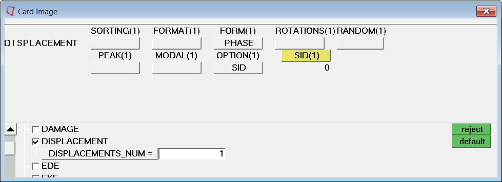
For Card Image, select FREQi from the
drop-down menu.
Check the FREQ1 option and enter
1 in the NUMBER_OF_FREQ1
field.
Update the following fields in the pop-out window.
For F1, enter 20.0.
For DF, enter 20.0.
For NDF, enter 49.
Click Close.
This provides a set of
frequencies beginning with 20.0, incremented by 20.0
and 49 frequencies increments.
Create a Load Step
In the Model Browser, right-click and
select Create > Load Step.
A default load step template is now displayed in the
Entity Editor below the
Model Browser.
For Name, enter subcase1.
For Analysis type, select Freq.resp (direct) from the drop-down
menu.
For SPC, select Unspecified > Loadcol.
From the Select Loadcol dialog, select
SPCS.
For DLOAD, select rload2 from the Select Load
Step Inputs pop-out window.
For FREQ, click Unspecified > Loadcol
From the Select Loadcol dialog, select
freq1.
An OptiStruct subcase has been
created which references the constraints in the load
collector spc and the unit load in the load
collector step input rload2 with a set of
frequencies defined in load collector freq1
Create a Set of Nodes
In the Model Browser, right-click and select Create > Set.
For Name, enter SETA.
For Card Image, select None.
Leave the Set Type switch set to non-ordered type.
For Entity IDs, select Nodes from the selection
switch.
Click Nodes and select nodes with IDs 15, 17 and 19.
Click proceed.
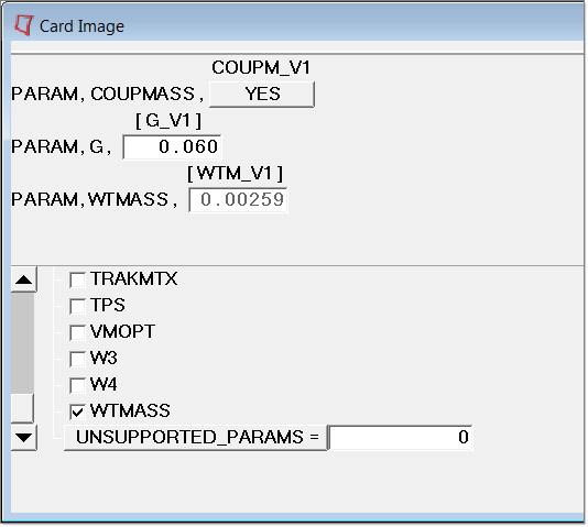
出力セットとマスファクターの生成
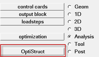
Setup > Create > Control Cardsをクリックし、Control Cardsパネルを開きます。

 を選択します。
Select OptiStruct Fileブラウザが開きます。
を選択します。
Select OptiStruct Fileブラウザが開きます。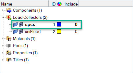
 をクリックします。
 をクリックします。
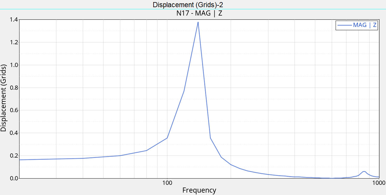
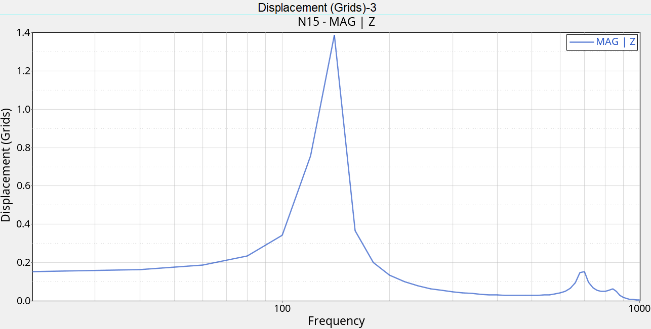
これで、Subcase 1 (subcase1) - Displacement of grid 17を示す、ページ 2が表示されます(図 8)。
をクリックします。
これで、Subcase 1 (subcase1) - Displacement of grid 17を示す、ページ 2が表示されます(図 8)。