In this tutorial, you will learn how to assemble the vehicle for full vehicle
simulations using Assembly Wizard and how to attach the driver using Task
Wizard.
The Altair Driver is a set of MotionView models and libraries that allow MotionView users to control and script vehicle events.
Event example include the following:
Constant Radius Cornering
Single Lane Change
Double Lane Change
User Defined Path Following
Fish Hook Event, etc.
This is achieved by creating an interface to the five vehicle inputs:
Steering
Throttle
Gear
Brake
Clutch
You can use the Altair Driver to simulate any number of
full vehicle events using multiple features:
Scripting: break up the simulation into different maneuvers; select the
controllers for vehicle inputs and define conditions that end each
maneuver.
Open-loop, closed-loop, and user-defined controllers to control.
Longitudinal speed or acceleration.
Vehicle path or lateral acceleration.
Switching controllers during a simulation.
Defining path and speed profiles parametrically, in a table, or by
referencing a data file.
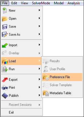
Assemble the Vehicle
In this step, you will assemble the vehicle using the Assembly Wizard.
Start a new MotionView session.
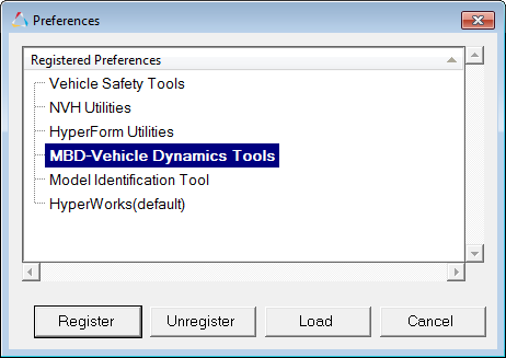
Ensure the MBD-Vehicle Dynamics Tools preference file loaded is for all of the
MotionView functionality of the Advanced Driver
to work properly.
Figure 1. Figure 2.
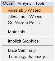
From the menu bar, select Model > Assembly Wizard.
Figure 3. In Script an Open Loop Acceleration Event, a linear
torque map powertrain will be used to avoid the complexity of adding controllers
for gear and clutch.
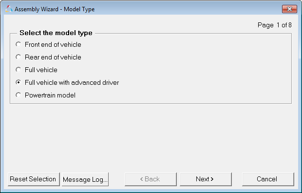
Select the Full vehicle with advanced driver
option.
This takes care of all the dependencies of the advanced driver.Figure 4.
Click Next.
Choose the default selections in the following Assembly Wizard pages.
Page
Label
Selection
Default (Yes/No)
1
Model type
Full vehicle with
driver
No
2
Driveline configuration
Front wheel drive
Yes
3
Vehicle body
Body
Yes
4
Instrumentation
Instrumentation
Yes
5
Front subframe
None
Yes
6
Front suspension
Frnt macpherson susp (1 pc. LCA)
Yes
7
Steering Linkages
Rackpin steering
Yes
8
Rear subframe
None
Yes
9
Rear suspension
Rear quadlink susp
Yes
10
Powertrain
Linear torque map powertrain
Yes
11
Signal generator
Driver signal generator
Yes
12
Tires
Auto Tires
Yes
13
Steering column
Steering column 1 (not for Abaqus)
Yes
14
Steering boost
None
Yes
15
Front struts
Frnt strut (with inline jts)
Yes
16
Front stabilizer bars
None
Yes
17
Rear struts
Rear strut (with inline jts)
Yes
18
Rear stabilizer bars
None
Yes
19
Front jounce bumpers
None
Yes
20
Front rebound bumpers
None
Yes
21
Rear jounce bumpers
None
Yes
22
Rear rebound bumpers
None
Yes
23
Disk brakes
Disk brakes
Yes
24
Front Driveline
Independent fwd
Yes
25
Driver System
Altair Driver
Yes
26
Next
Finish
No
Add Driver Analysis
In this step, you will use the Task Wizard to load the driver analysis.
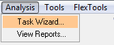
From the menu bar, select Analysis > Task Wizard.
Figure 5.
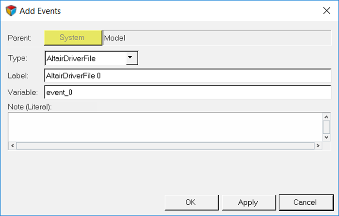
Select AltairDriverFile from the Type drop-down
menu.
Figure 6.
Tip:
Selecting (Altair Driver
icon) will open up the Altair Driver panel.
This automatically resolves all of the vehicle attachments for the
Altair Driver.
Figure 7.
Selecting the AltairDriverFile 0 will open up the driver event panel.
Selecting the Event Editor button will open the Altair Driver
File dialog.
The Altair Advanced Driver is
added to the browser tree.
Write an Altair Driver File Driving Event
In this step, you will script an open loop acceleration, open loop sinusoidal
steering, and an open loop driven braking event.
Driver requires an event script or the Altair driver file (ADF) to run any driving event. ADF can be
edited using any text editor or by clicking the Edit Driver File
button on the driver panel.
Script an Open Loop Acceleration Event
In this step, you will script an event with 50% throttle, 0% brake and 0 steering
angle.
An event can be broken down into smaller sub-events or maneuvers. You will model this
as a single maneuver event.
Figure 8.
Open any text editor and copy and paste the following text into it.
Important: All blank lines must be removed prior to saving the
file.
Tip: Read through the comments for a better understanding of what is
written in the ADF.
$-----------------------------------------------------------------ALTAIR_HEADER$ This block is required for version control[ALTAIR_HEADER]
FILE_TYPE = 'ADF'
FILE_VERSION = 1.0
FILE_FORMAT = 'ASCII'
$--------------------------------------------------------------------------UNITS$In this block we specify the units in which this file should be read[UNITS](BASE)
{length force angle mass time}
'meter' 'newton' 'radians' 'kg' 'sec'
$--------------------------------------------------------------------VEHICLE_IC$In this block we specify the initial conditions specifically initial speed of the$vehicle with respect to the vehicle IC marker in the driver attachments[VEHICLE_INITIAL_CONDITIONS]
VX0 = -20.0
VY0 = 0.0
VZ0 = 0.0
$--------------------------------------------------------------STEERING_STANDARD$This block specifies the saturation and cutoff frequency for the low pass filter for$steering output signal. These signals are global and are active for the entire event[STEER_STANDARD]
MAX_VALUE = 3.141593
MIN_VALUE = -3.141593
SMOOTHING_FREQUENCY = 10.0
INITIAL_VALUE = 0.0
$--------------------------------------------------------------THROTTLE_STANDARD$This block specifies the saturation and cutoff frequency for the low pass filter for$throttle output signal[THROTTLE_STANDARD]
MAX_VALUE = 1.0
MIN_VALUE = 0.00
SMOOTHING_FREQUENCY = 10.0
INITIAL_VALUE = 0.5
$---------------------------------------------------------------BRAKING_STANDARD$This block specifies the saturation and cutoff frequency for the low pass filter for$brake output signal[BRAKE_STANDARD]
MAX_VALUE = 1.0
MIN_VALUE = 0.0
SMOOTHING_FREQUENCY = 10.0
INITIAL_VALUE = 0.0
$-----------------------------------------------------------------MANEUVERS_LIST$This block provides the list of all the maneuvers, simulation time for each maneuver$maximum solver step size (hmax) and print interval[MANEUVERS_LIST]
{ name simulation_time h_max print_interval}
'MANEUVER_1' 5.0 0.01 0.01
$---------------------------------------------------------------------MANEUVER_1[MANEUVER_1]$This block provides the ties controllers to each driver output
TASK = 'STANDARD'
(CONTROLLERS)
{DRIVER_SIGNAL PRIMARY_CONTROLLER ADDITIONAL_CONTROLLER}
STEER OL_STEER_0 NONE
THROTTLE OL_0.5 NONE
BRAKE OL_0 NONE
$---------------------------------------------------------OL_STEER
$This is controller block containing all the information required by
$the driver to construct the controller. Different controllers have
$different requirements. Here we are using open loop constant type
$of controller.[OL_STEER_0]
TAG = 'OPENLOOP'
TYPE = 'CONSTANT'
VALUE = 0.0
$---------------------------------------------------------OL_BRAKE[OL_0]
TAG = 'OPENLOOP'
TYPE = 'CONSTANT'
VALUE = 0.0
$---------------------------------------------------------OL_THROTTLE[OL_0.5]
TAG = 'OPENLOOP'
TYPE = 'CONSTANT'
VALUE = 0.5
Save the file.
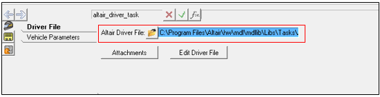
Source the file in the Altair Driver File
browser.
Figure 9.
Note: The Edit driver file button can be used to edit the file.
Click to run the simulation.
After the simulation is over and the solver creates the h3d and plt files, from
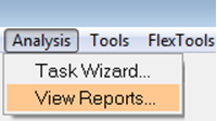
the menu bar, click Analysis > View Reports.
Figure 10.
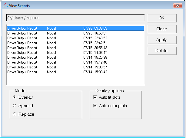
Select the recent run in the View Reports dialog and click
OK.
Figure 11.
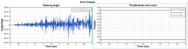
The noise in the steering is numerical error of negligible magnitude – 0 for
all practical purposes. Throttle is constant at 0.5 (driver throttle, brake and
clutch outputs are normalized so, 50%) and brake is constant at 0.
Figure 12.
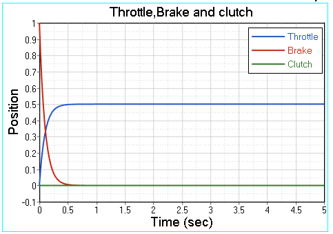
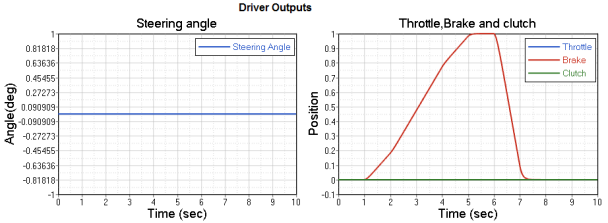
Next we will try slightly different initial conditions. We will start the
throttle at 0 and brake at 100%. Click the Edit Driver
File button to open up the file editor.
Change the INITIAL_VALUE attribute in the THROTTLE_STANDARD block in the ADF,
from 0.5 to 0.
Now, we see that throttle and brake start from respective initial values and
step up to the controller outputs. The time taken to step up is roughly
(5x1/SMOOTHING_FREQUENCY).
Figure 13.
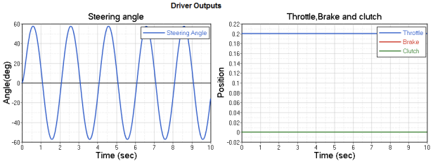
Model an Open Loop Sinusoidal Steering Event
In this step, you will model a simple event with constant 20% throttle, constant 0%
throttle and sinusoidal steering input with amplitude of 60 degrees (∏/3 radians) and
frequency of 0.5 Hz.
Open any text editor and copy and paste the following text into it.
Important: All blank lines must be removed prior to saving the
file.
$-----------------------------------------------------------------ALTAIR_HEADER[ALTAIR_HEADER]
FILE_TYPE = 'ADF'
FILE_VERSION = 1.0
FILE_FORMAT = 'ASCII'
$--------------------------------------------------------------------------UNITS[UNITS](BASE)
{length force angle mass time}
'meter' 'newton' 'radians' 'kg' 'sec'
$--------------------------------------------------------------------VEHICLE_IC[VEHICLE_INITIAL_CONDITIONS]
VX0 = -20.0
VY0 = 0.0
VZ0 = 0.0
$--------------------------------------------------------------STEERING_STANDARD[STEER_STANDARD]
MAX_VALUE = 3.141593
MIN_VALUE = -3.141593
SMOOTHING_FREQUENCY = 10.0
INITIAL_VALUE = 0.0
$--------------------------------------------------------------THROTTLE_STANDARD[THROTTLE_STANDARD]
MAX_VALUE = 1.0
MIN_VALUE = 0.00
SMOOTHING_FREQUENCY = 10.0
INITIAL_VALUE = 0.2
$---------------------------------------------------------------BRAKING_STANDARD[BRAKE_STANDARD]
MAX_VALUE = 1.0
MIN_VALUE = 0.0
SMOOTHING_FREQUENCY = 10.0
INITIAL_VALUE = 0.0
$-----------------------------------------------------------------MANEUVERS_LIST[MANEUVERS_LIST]
{ name simulation_time h_max print_interval}
'MANEUVER_1' 10.0 0.01 0.01
$---------------------------------------------------------------------MANEUVER_1[MANEUVER_1]
$This block provides the ties controllers to each driver output
TASK = 'STANDARD'
(CONTROLLERS)
{DRIVER_SIGNAL PRIMARY_CONTROLLER ADDITIONAL_CONTROLLER}
STEER OL_STEER NONE
THROTTLE OL_THROTTLE NONE
BRAKE OL_BRAKE NONE
$---------------------------------------------------------OL_STEER.$SIGNAL_CHANNEL tells the driver which solver variable in Signal Generator to over-ride$with the EXPRESSION value. The EXPRESSION should be consistent with MOTIONSOLVE.[OL_STEER]
TAG = 'OPENLOOP'
TYPE = 'EXPRESSION'
SIGNAL_CHANNEL = 0EXPRESSION = 'DTOR(60)*SIN(2*PI*0.5*TIME)'$---------------------------------------------------------OL_THROTTLE [OL_THROTTLE]
TAG = 'OPENLOOP'
TYPE = 'CONSTANT'
VALUE = 0.2
$---------------------------------------------------------OL_BRAKE[OL_BRAKE]
TAG = 'OPENLOOP'
TYPE = 'CONSTANT'
VALUE = 0.0
Run the simulation and study the results.
Figure 14.
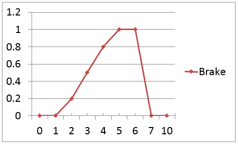
Model an Open Loop Curve Driven Braking Event
In this step, you will model a simple event with braking signal as a
curve.
Figure 15.
Open text editor and copy and paste the following text into it.
Important: All blank lines must be removed prior to saving the
file!
$-----------------------------------------------------------------ALTAIR_HEADER[ALTAIR_HEADER]
FILE_TYPE = 'ADF'
FILE_VERSION = 1.0
FILE_FORMAT = 'ASCII'
$--------------------------------------------------------------------------UNITS[UNITS](BASE)
{length force angle mass time}
'meter' 'newton' 'radians' 'kg' 'sec'
$--------------------------------------------------------------------VEHICLE_IC[VEHICLE_INITIAL_CONDITIONS]
VX0 = -20.0
VY0 = 0.0
VZ0 = 0.0
$--------------------------------------------------------------STEERING_STANDARD[STEER_STANDARD]
MAX_VALUE = 3.141593
MIN_VALUE = -3.141593
SMOOTHING_FREQUENCY = 10.0
INITIAL_VALUE = 0.0
$--------------------------------------------------------------THROTTLE_STANDARD[THROTTLE_STANDARD]
MAX_VALUE = 1.0
MIN_VALUE = 0.00
SMOOTHING_FREQUENCY = 10.0
INITIAL_VALUE = 0.0
$---------------------------------------------------------------BRAKING_STANDARD[BRAKE_STANDARD]
MAX_VALUE = 1.0
MIN_VALUE = 0.0
SMOOTHING_FREQUENCY = 10.0
INITIAL_VALUE = 0.0
$-----------------------------------------------------------------MANEUVERS_LIST[MANEUVERS_LIST]
{ name simulation_time h_max print_interval}
'MANEUVER_1' 10.0 0.001 0.01
$---------------------------------------------------------------------MANEUVER_1[MANEUVER_1]$This block provides the ties controllers to each driver output
TASK = 'STANDARD'
(CONTROLLERS)
{DRIVER_SIGNAL PRIMARY_CONTROLLER ADDITIONAL_CONTROLLER}
STEER OL_STEER NONE
THROTTLE OL_THROTTLE NONE
BRAKE OL_BRAKE NONE
$---------------------------------------------------------OL_STEER.
$SIGNAL_CHANNEL tells the driver which solver variable in Signal Generator to over-ride
$with the EXPRESSION value. The EXPRESSION should be consistent with MOTIONSOLVE.[OL_STEER]
TAG = 'OPENLOOP'
TYPE = 'CONSTANT'
VALUE = 0.0
$---------------------------------------------------------OL_THROTTLE[OL_THROTTLE]
TAG = 'OPENLOOP'
TYPE = 'CONSTANT'
VALUE = 0.0
$---------------------------------------------------------OL_BRAKE[OL_BRAKE]
TAG = 'OPENLOOP'
TYPE = 'CURVE'
BLOCK = 'BRAKE_CRV'
$---------------------------------------------------------CURVE_DATA[BRAKE_CRV]
INDEPENDENT_VARIABLE = 'TIME'
DEPENDENT_VARIABLE = 'BRAKE_SIGNAL'
INTERPOLATION = 'LINEAR'
{TIME BRAKE_SIGNAL}
0 0
1 0
2 0.2
3 0.5
4 0.8
5 1.0
6 1.0
7 0
10 0

 (Altair Driver
icon) will open up the Altair Driver panel.
This automatically resolves all of the vehicle attachments for the
Altair Driver.
(Altair Driver
icon) will open up the Altair Driver panel.
This automatically resolves all of the vehicle attachments for the
Altair Driver.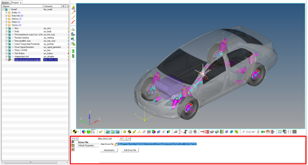
 Note: The Edit driver file button can be used to edit the file.
 to run the simulation.