In this tutorial, you will learn how to use the Soft Soil Tire and
Road model, create moving carpet road graphics, run the model in MotionSolve, and view the simulation results.
The Soft Soil Tire model implementation is used for simulating vehicles running on
off-road conditions representing the dynamic behavior of a tire on a compressible
surface.
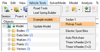
Add Example Pickup Truck Model
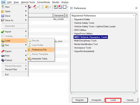
In a MotionView session, on the menu bar, click File > Load > Preference File to open the Preferences dialog.
Select MBD-Vehicle Dynamics Tools.
Click Load.
Figure 1.
On the menu bar, click Vehicle Tools > Example models > Pickup Truck.
Figure 2.
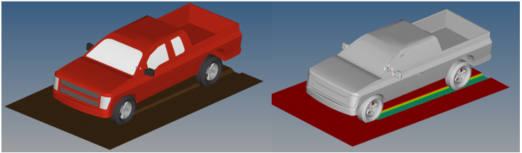
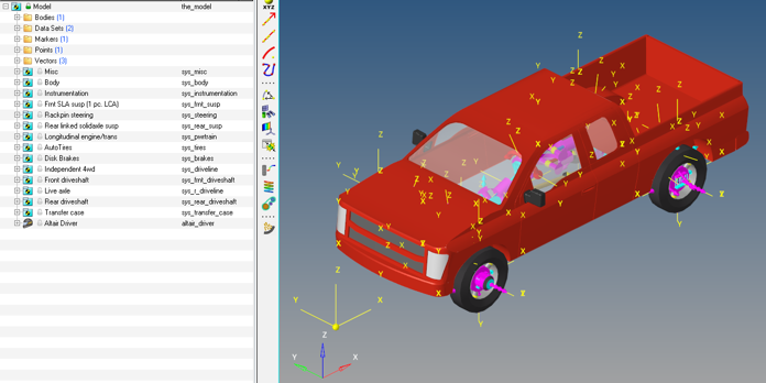
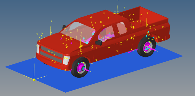
The pickup truck model is displayed in the modeling window.Figure 3.
Add Moving Carpet Graphics
The carpet road is used to represent graphically the soft soil terrain. It creates a
flat surface which shows the soil sinkage while post processing the animation in
HyperView. The carpet is attached to the carpet
marker, if the marker moves along with the vehicle, the carpet graphics follows the
vehicle showing the deformation of the soft soil in the region where the carpet is
in contact with tires. If the carpet marker is attached to the ground body or any
other static body, the carpet road graphic will also be static, and the soil sinkage
is seen when the vehicle goes over it.
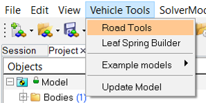
From the Vehicle Tools menu, select Road Tools.
Figure 4.
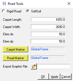
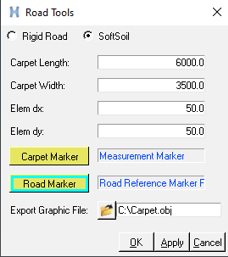
From the Road Tools dialog, select the SoftSoil
option.
Figure 5.
The carpet length and width are automatically populated to enclose the tires.
These can be changed as per the user’s requirement.
Change the Carpet Length to 6000mm and Carpet Width to
3500mm.
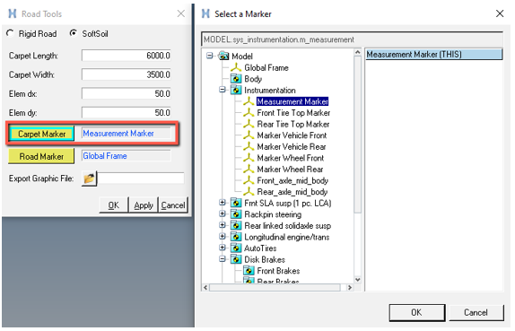
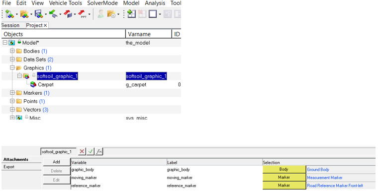
Click the Carpet Marker collector and select
Measurement Marker.
Figure 6. This marker moves with the vehicle.
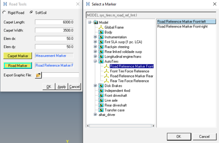
Click the Road Reference Marker collector and select
Road Marker.
The road reference marker is the stationary marker which serves as a reference
for the carpet marker.Figure 7.
Save the .obj file in the Export Graphic File field.
Figure 8.
Click OK to display the carpet graphics.
Figure 9.
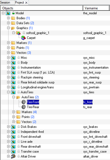
A corresponding graphic system is created in the model tree named
softsoil_graphic_1 (1 denotes the count number of
soft soil graphics). The markers can also be changed from the graphics
panel.
Figure 10.
Select the Soft Soil Tire and Road
The Soft Soil Tire and Road have to be selected from the AutoTire panel. Some
examples are available at:
<Installation>\hwdesktop\hw\mdl\autoentities\properties\Tires\
ALTAIR_SOFTSOIL.
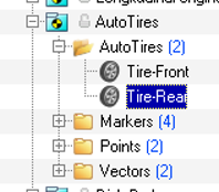
Select the AutoTirePair-Front from the model tree in the browser.
Figure 11.
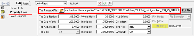
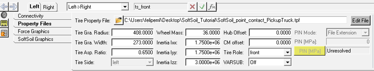
From the Property Files tab, click the Tire Property
File file browser and select
SoftSoil_point_contact_200_45_R18.tpf from
<Installation>\hwdesktop\hw\mdl\autoentities\properties\Tires\
ALTAIR_SOFTSOIL\TireLibrary.
Figure 12.
Note: The tire file in the installation folder can be
edited to match the pickup truck tire properties.
Click on the Edit File button to modify the SoftSoil
Tire parameters.
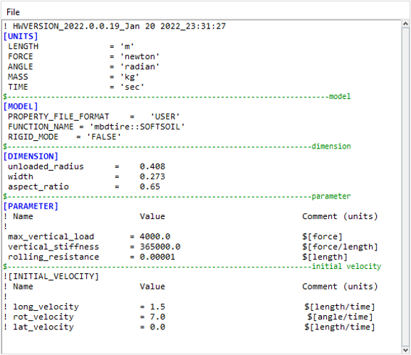
Edit the Tire parameters as follows:
unloaded_radius =
0.408
width =
0.273
aspect_ratio =
0.65
max_vertical_load =
4000.0
vertical_stiffness =
365000.0
Figure 13.
Click on File and save the modified property file in
your <working directory>.
The AutoTire panel is updated with the values specified in the Tire property
file.Figure 14.
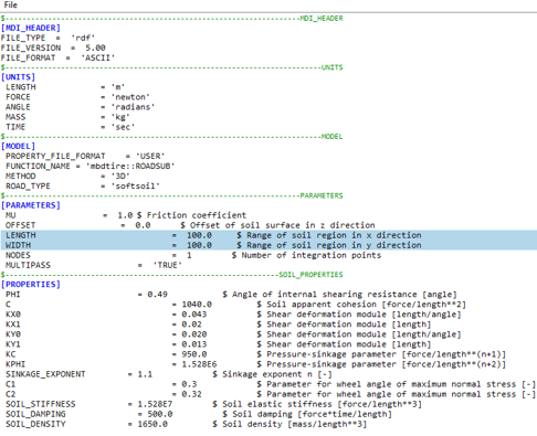
Click on Road Property File and select
dry_sand.rdf
from<Installation>\hwdesktop\hw\mdl\autoentities\properties\Tires\
ALTAIR_SOFTSOIL\RoadLibrary.
Click on Edit File to modify the SoftSoil Road
parameters.
Modify the Length and Width of
the road to 100m.Figure 15.
Note: The Length and Width parameters define the
limit of the soft-soil road.
Click on File and save the modified property file in
your <working directory>.
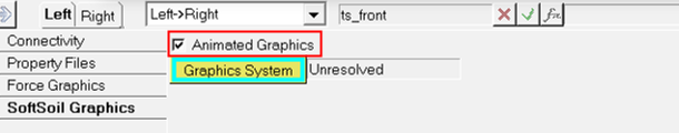
Click on SoftSoil Graphics in the AutoTire panel and
select the Animated Graphics option to add moving carpet
graphics for the animation.
Figure 16.
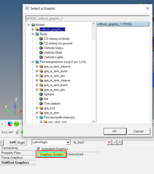
Click on the Graphics System collector and select
softsoil_graphic_1.
Figure 17.
Note: Only the Graphics Systems generated using the road
tools - SoftSoil option should be selected. Any other Graphics System will
show an error message.
The animation graphics can be switched on from any of the front or rear
AutoTire panels. As all AutoTires are rolling over the same soil patch, the soil
deformation will be shown for all the tires on the carpet even if the Animation
Graphics option was selected in only one AutoTire.
Select AutoTirePair-Rear from the browser.
Figure 18.
Under Property Files, click on Tire Property File and
select the modified Tire file saved in Step 4.
Click on Road Property File and select the modified Road
file saved in Step 7.
Note: It is not necessary to edit the Soft Soil Graphics
tab since it is already done for the Front tires.
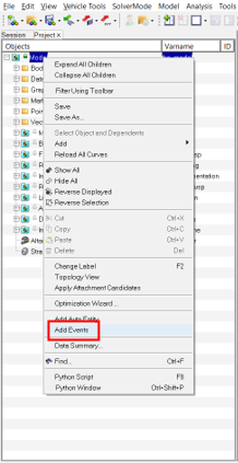
Add an Event
Right-click on Model in the browser and select
Add Events from the context menu.
Figure 19.
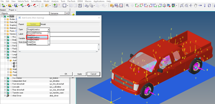
Select Straight-Line Acceleration from the events list
and click OK.
Figure 20.
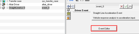
Click on the Event Editor to modify the event parameters
and run the model.
Figure 21.
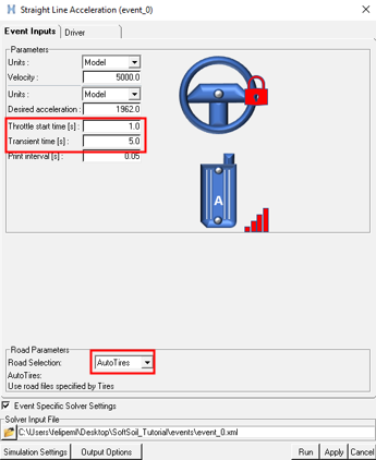
Change the Throttle start time to 1.0
sec, Transient time to 5.0
sec, and select AutoTires from the
Road Selection drop-down menu. Enter the path
location for simulation files and click Run.
Figure 22.
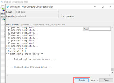
When the simulation completes, click on Results to view
the animation in HyperView.
Figure 23.
Post-Processing
A HyperView Session is opened with the Pickup Truck model
results.
Click the (Start/Pause Animation) button
on the Animation toolbar to view the animation and soil sinkage.
Figure 24.
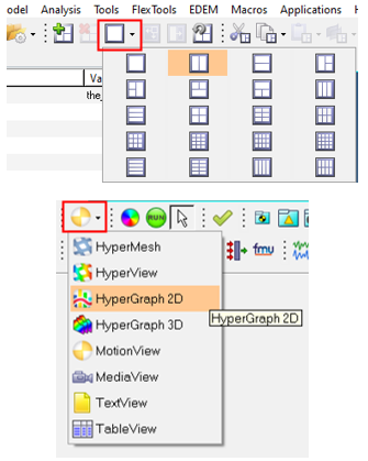
Add a second window in the same page and select HyperGraph 2D.
Figure 25.
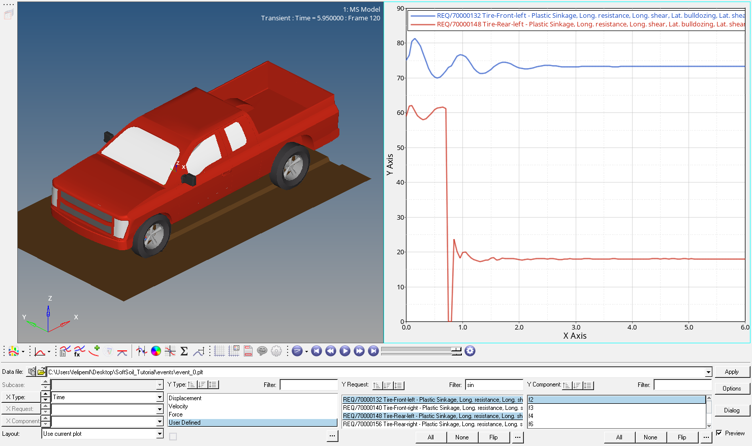
In HyperGraph, open .plt file
from the folder saved in Step 4/Sub-step 4.
In addition to the regular outputs available for AutoTires, there is an output
request to view the results specific to the soft soil.
For Y Type select User Defined,
then for Y request select AutoTirePair-
Tire-Front-Left - Plastic sinkage, … and
AutoTirePair- Tire-Rear-Left - Plastic sinkage, ….
Select F2 for Y component to
analyze the soil sinkage in the front and rear tire.
Figure 26.
The soft soil outputs are:
F2 – Plastic sinkage: Amount of permanent
deformation of soil after the tire has passed.
F3 – Long Resistance: Contribution of soil
normal stress to the longitudinal force.
F4 – Long Shear: Contribution of soil shear
stress to the longitudinal force.
F3 and F4 represent the tire longitudinal force, in other words the force
applied by the soil resisting the tire longitudinal movement.
F6 – Lat bulldozing: Lateral Bulldozing force
acting on tire contact patch.
F7 – Lat Shear force: Contribution of soil shear
stress to the lateral force.
F6 and F7 represent the tire lateral force, in other words the force applied
by the soil resisting the tire lateral movement.
F8 – Tire Sinkage: Soil deformation at the tire
contact patch.
For additional information on tire-soft soil, see the Soft Soil Tire Model topic.

 (Start/Pause Animation) button
on the Animation toolbar to view the animation and soil sinkage.
(Start/Pause Animation) button
on the Animation toolbar to view the animation and soil sinkage.