Create Members
Use the Members tool to create members between two joints.
-
From the Skeleton ribbon, click the Members tool.
図 1. 
- Select a starting joint.
-
Select an ending joint or a symmetry plane.
Sections are created in between the two.
図 2. . The primary joint is selected and then the symmetry plane. The preview shows the sections in symmetry, these can be edited as required . 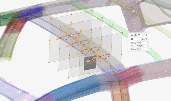
-
Click
 on the ガイドバー to define
options.
on the ガイドバー to define
options.
- Number of control points
- The number of sections that are created throughout the symmetric member creation.
- Cut planes
- The default length and width of the cut plane.
- Realize member
- Create 1D mesh and the associated beam sections based on the cut plane sections.
-
Resize and reposition the planes in the following ways:
- Click and drag the boxes at the edges of the plane(s) to resize and capture the appropriate structure.
- Toggle
 in the マイクロダイアログ to
move each plane globally. Use the drop-down menu to control which section(s)
display the manipulator.
in the マイクロダイアログ to
move each plane globally. Use the drop-down menu to control which section(s)
display the manipulator. - Click
 in the マイクロダイアログ to
align the last member created. Press Ctrl + Z to
undo.
in the マイクロダイアログ to
align the last member created. Press Ctrl + Z to
undo.
- If the member is being realized , define the 1D mesh and the associated beam sections.
- オプション:
Click the Exclude selector on the ガイドバー then pick entities to exclude from the member if
required.
図 3. . The member, 1D mesh, and beam sections are created and applied appropriately 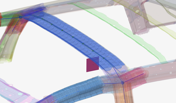
-
ガイドバーで、下記のオプションのいずれか1つをクリックします:
 - 適用し、ツールを開いたままにする
 - 適用し、ツールを閉じる
 – 適用せずにツールを終了する
Assign Beam Sections to Members or Member Sections
Use the Assign tool if a member is created without a beam section or the beam section needs to be changed.
-
From the Skeleton ribbon, Member tool group, click the
Assign tool.
図 4. 
- Select the members or member sections.
- Select the beam section to assign.
-
ガイドバーで、下記のオプションのいずれか1つをクリックします:
- - 適用し、ツールを開いたままにする
- - 適用し、ツールを閉じる
- – 適用せずにツールを終了する